Servo actuator with self positioning rotor and method

a self-positioning, actuator technology, applied in the direction of motor/generator/converter stopper, dynamo-electric converter control, gearing, etc., can solve the problems of increasing the cost and size of the motor winding and drive, limiting the speed of permanent magnet motors, and often compromising cycle times

Active Publication Date: 2009-01-27
TOL O MATIC
View PDF12 Cites 34 Cited by
  • Summary
  • Abstract
  • Description
  • Claims
  • Application Information

AI Technical Summary

Benefits of technology

[0020]In doing this, the proportional torque constant is also higher, hence substantially reducing the current requirements at high forces. Reducing the current requirement allows for smaller and less costly motor components and amplifiers. Reduction of current losses greatly reduces losses in the motor windings characterized by the current squared times the winding resistance. Hence the motor runs cooler or the continuous operation can be elevated. The current invention effectively provides operating speeds that are twice those of current designs or will reduce current requirements for a given application by over 50 percent. The approach to field weakening set forth by the teachings of the present invention allow the rotor assembly to shift relative to the stator assembly as the screw driven member encounters loading.
[0021]It is a further object of the invention to leverage the shifting of the rotor assembly to supply a very precise, low cost, compact means of monitoring actual supplied force without the need for an expensive force sensor and signal conditioner. Many of the applications specified for this device require a means of monitoring actual delivered force relative to position for quality control purposes. Through a secondary spring resisting axially shift of the rotor assembly, a low cost, short stroke linear position sensor will provide the required force feedback.

Problems solved by technology

Permanent magnet motors are typically limited in speed by the back electro-motive force (bemf) generated with respect to the available driving voltage.
For this reason cycle times are often compromised due to less than desirable approach speeds.
Additionally, extremely high currents are often required to deliver sufficient force, increasing both the cost and size of the motor windings and drive.
This approach is cumbersome and requires relatively high waste currents to be injected into a device where efficiency is important and heat dissipation is often a challenge.
Very few of these are in production due to various limitations, primarily in cost to manufacture.
The complexity of these devices is primarily due to the desire to overcome the limitations in permanent magnet motors for purely rotary applications.
This adds significant cost and complexity to a rotary motor.
Without the ability to field weaken in applications requiring high forces / low speeds and high speeds / low forces motors and drives are larger than necessary, operate far from peak efficiency for the application, and are more costly than necessary.
In applications where high force / low speed and high speed / low force are required, operation does not take advantage of the peak horsepower capability of the typical permanent magnet motor.
By limiting the Ke, the Kt is also limited.
Motor costs, as well as drive costs, are typically high to supply the necessary currents.
The need for this force monitoring is often beyond that achieved through observing the applied current, since friction and many other system inefficiencies and tolerances influence the precision that can be obtained from purely monitoring current.
While these devices provide high speeds and high forces their limitations are in that they are only capable of very crude positional, speed, and force control, they are very bulky systems, and due to the use of hydraulic fluid they can be very messy over time as seals wear and begin to leak.
These motors are the best suited motors for precision, linear reciprocating devices due to their high torque density, high efficiency, rapid dynamic response for precise position, velocity and force control, and limited maintenance.
Permanent magnet, brushless motors are typically limited in speed due to the back electromotive force (bemf) produced by the magnets.

Method used


Image

  • Servo actuator with self positioning rotor and method
  • Servo actuator with self positioning rotor and method
  • Servo actuator with self positioning rotor and method

Examples


Embodiment Construction

)

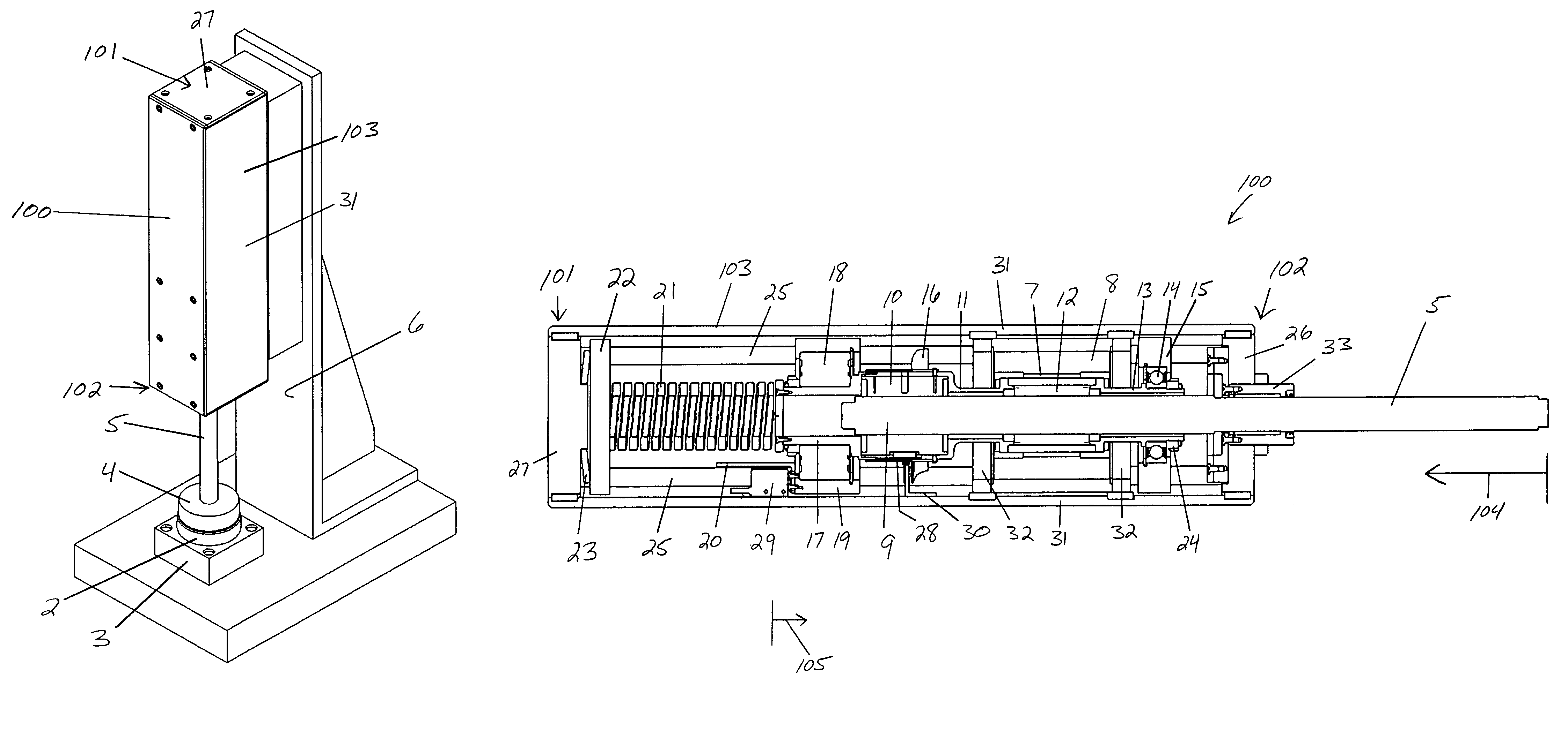
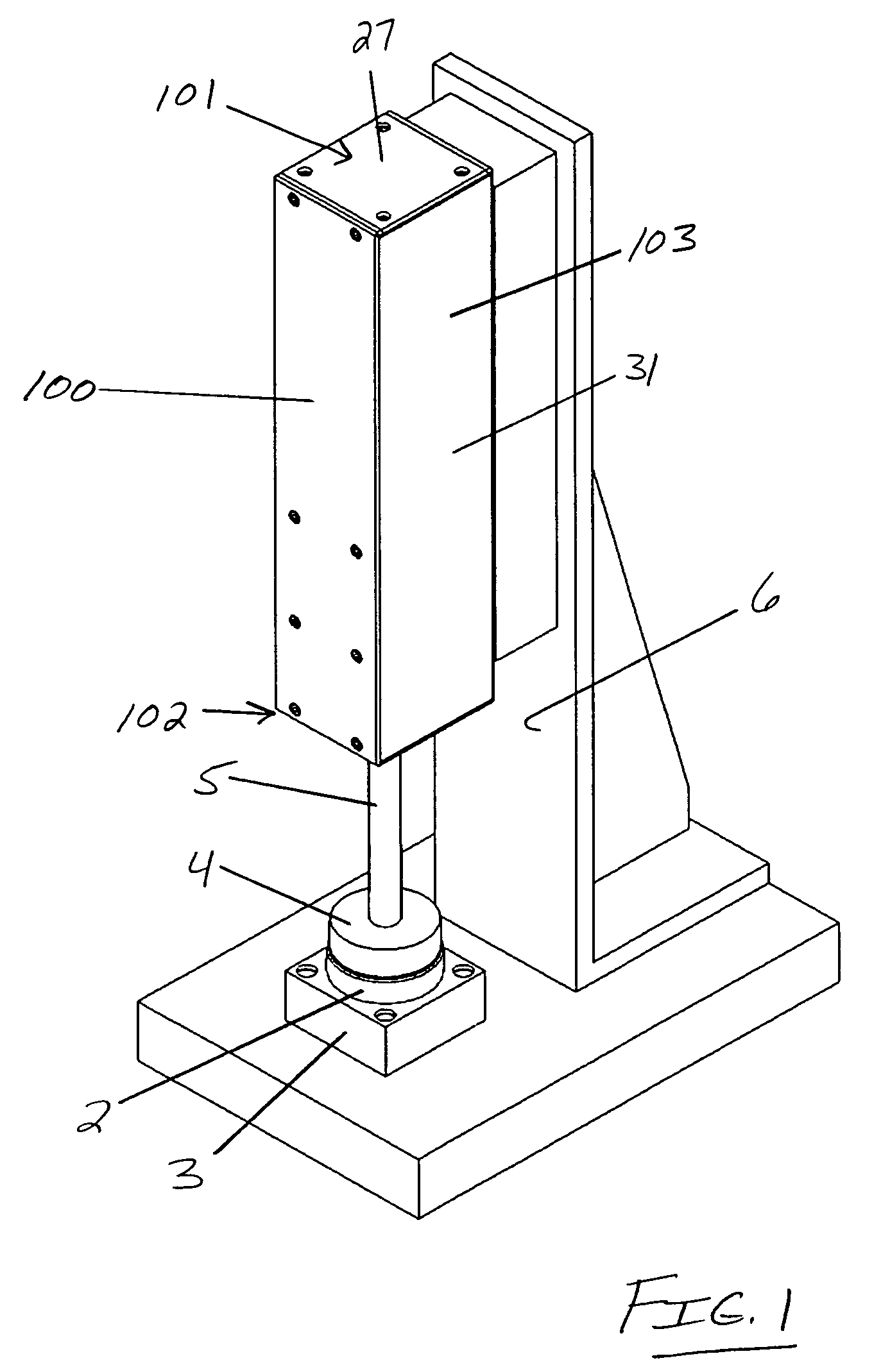
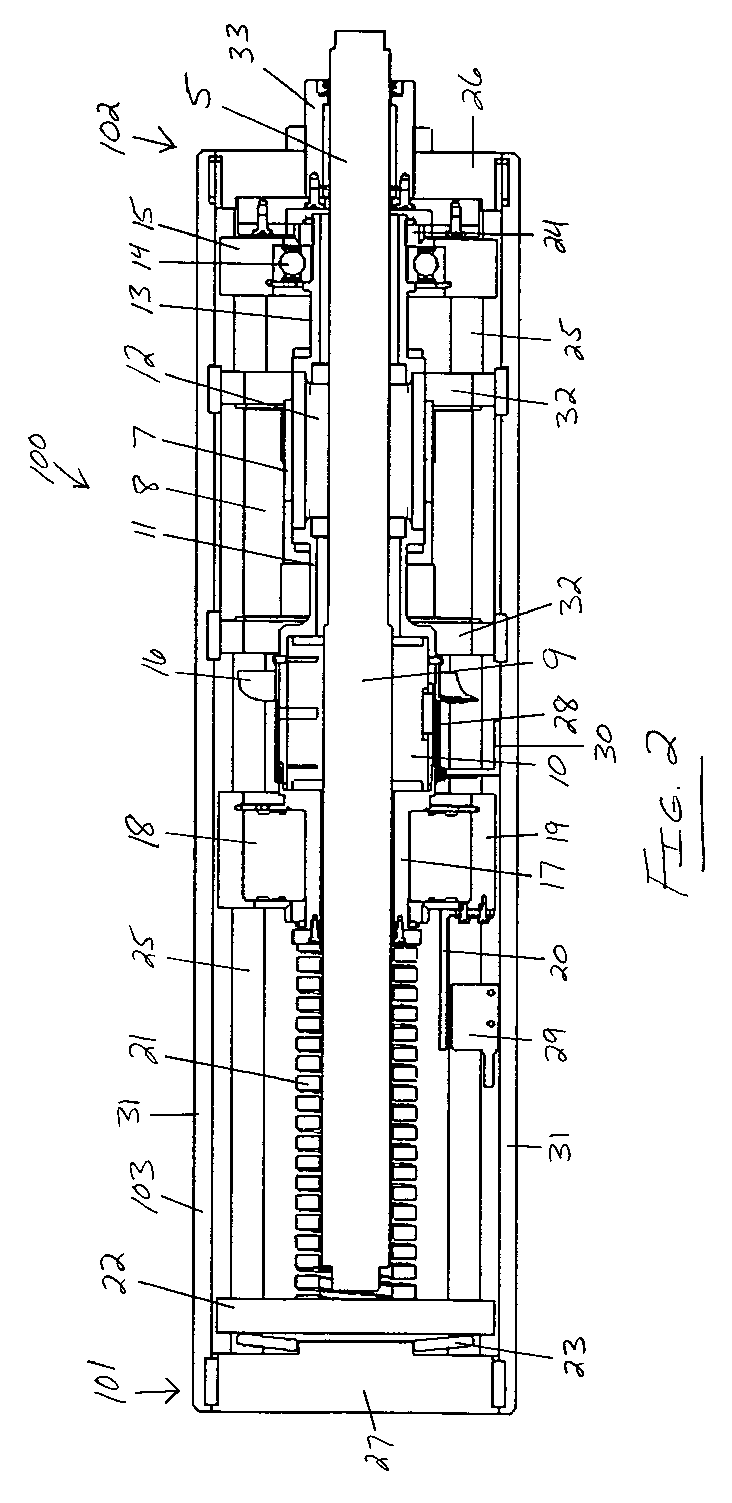
[0029]Referring now to the drawings, the preferred embodiment of the present invention generally concerns a servo actuator or linear actuator 100 intended for industrial applications including but not limited to piercing, crimping, pressing, trimming, forming, flaring, clamping, bending, coining, marking, and riveting. FIG. 1 shows a typical bearing press application. The linear actuator 100 of the current invention is shown extended to a point where a bearing 2 is initially being pressed into a receiving block 3. A bearing press tool 4 is directly attached to a screw thrust rod 5 of the linear actuator 100. A press frame 6 supports the linear actuator 100 relative to the pressing operation.

[0030]Referring to FIG. 1, it should be understood that the screw thrust rod 5 of linear actuator 100 would extend very rapidly until the bearing press tool 4 encountered loading generated by the resistance of pressing the bearing 2 into the bearing receiving block 3. The foregoing scenario may ...


PUM


Abstract

A linear actuator is provided with an integral permanent magnet, brushless motor capable of axial, self adjustment of the rotor position within the stator for field weakening. Axial displacement of the rotor within the stator allows for significantly improved speed performance from aligned rotor / stator components during light axial loading. Upon contact with a load, the screw and nut, as an integral part of the motor rotor, self align to fully engage within the stator for generation of high forces with minimal current. This axial shift can further be used as a high precision, low cost measure of the force applied for quality assurance purposes.

Description

BACKGROUND OF THE INVENTION[0001]1. Field of the Invention[0002]The present invention relates to an electrically powered linear actuator providing reciprocating, linear motion in applications with precise position and force requirements. More specifically it relates to an electrically powered linear actuator and certain methodology inherently taught thereby that addresses applications requiring high forces at moderate to low speeds to perform a specific operation, and high speeds at low forces at other portions of the cycle to quickly position and remove tooling. Typical applications include piercing, crimping, pressing, trimming, forming, flaring, clamping, bending, coining, marking, and riveting.[0003]2. Description of Prior Art[0004]Permanent magnet motors are typically limited in speed by the back electro-motive force (bemf) generated with respect to the available driving voltage. For this reason cycle times are often compromised due to less than desirable approach speeds. Addit...

Claims


Application Information

Patent Timeline
Patent Type & Authority Patents(United States)
IPC IPC(8): H02K41/00H02K7/06
CPCH02K7/06H02K7/12H02K11/0042Y10T74/18576Y10T74/18656H02K11/24
Inventor HOCHHALTER, KEITH W.SEILER, MICHAEL T.
Owner TOL O MATIC
Why Eureka
Try Eureka