Field weakening control apparatus for permanent magnet motor and electric power steering using same

a control apparatus and permanent magnet technology, applied in the direction of non-deflectible wheel steering, angular speed control of ac motors, underwater vessels, etc., can solve the problem that the maximum torque (limit torque) that the motor can output cannot be outpu

Active Publication Date: 2008-10-30
HITACHI ASTEMO LTD
View PDF6 Cites 34 Cited by
  • Summary
  • Abstract
  • Description
  • Claims
  • Application Information

AI Technical Summary

Benefits of technology

[0007]An aspect of the present invention provides a field weakening control apparatus for a permanent magnet synchronous motor that stably drives without going out of order in the weakened field region even if a torque reference specifying torque above the limit torque is input and that can output the limit torque even when the power supply voltage, frequency, and / or inductance vary.

Problems solved by technology

However, in the method of that Publication, variation in power supply voltage, variation in frequency, and variation in inductance are not taken into account, and hence maximum torque (limit torque) that the motor can output cannot be output.

Method used


Image

  • Field weakening control apparatus for permanent magnet motor and electric power steering using same
  • Field weakening control apparatus for permanent magnet motor and electric power steering using same
  • Field weakening control apparatus for permanent magnet motor and electric power steering using same

Examples


first embodiment

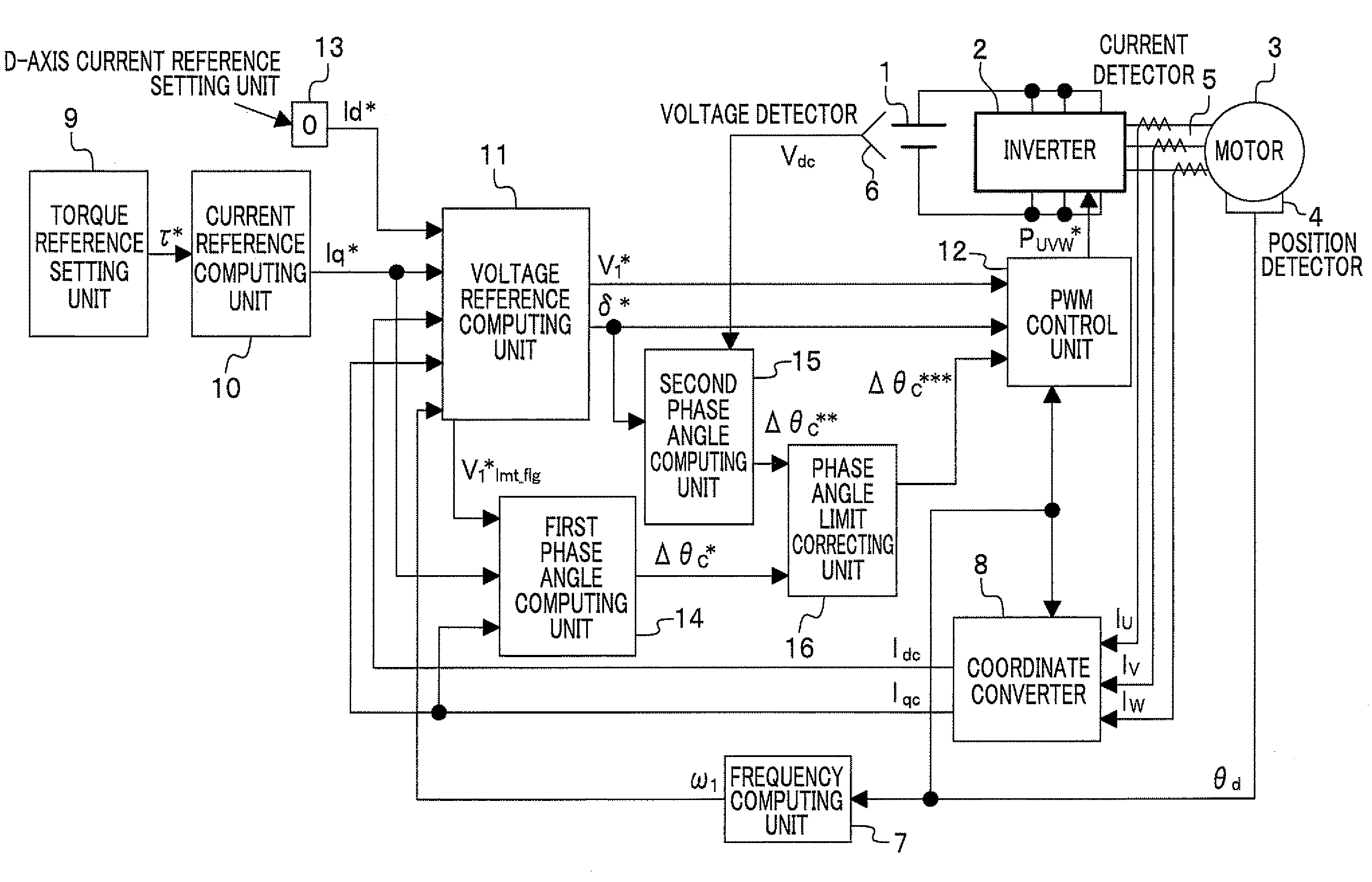
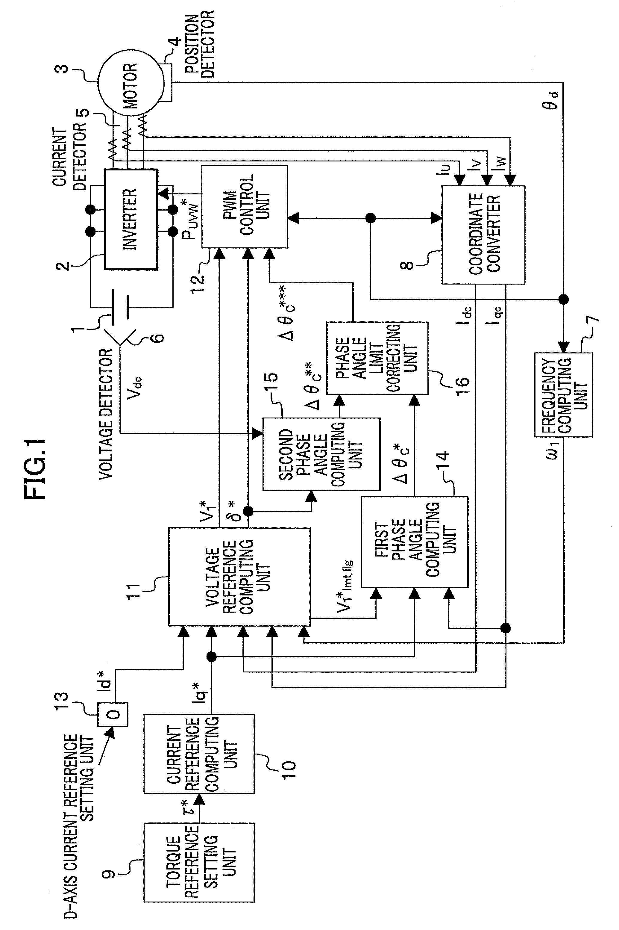
[0031]FIG. 1 shows a motor control system including a motor control apparatus according to a first embodiment of the present invention.

[0032]In FIG. 1, the motor control system includes a DC power supply 1 such as a battery for supplying electric power to an inverter 2; the inverter 2 for supplying three-phase AC power to a motor 3 according to three-phase PWM pulses Puvw*; the motor 3; a position detector 4 such as an encoder, a resolver, or a magnetic pole position sensor; a current detector 5 to detect a three-phase AC current; and a voltage detector 6 to detect a power supply voltage Vdc of the DC power supply 1 and a motor control apparatus.

[0033]The motor control apparatus includes a frequency computing unit 7 to compute a frequency value ω1 from a position detected value θd (rotational position of a rotor of the motor 3) detected by the position detector 4; a coordinate converter 8 to convert current values Iu, Iv, Iw detected by the current detector 5 with the position detec...

second embodiment

[0061]FIG. 7 shows a motor control system including a motor control apparatus according to a second embodiment of the present invention. Description of the blocks 1 to 5, 7 to 14, and 16 that are the same as in the first embodiment will be omitted. Although the second phase angle computing unit 15 of the first embodiment computes the second phase angle reference Δθc** based on the power supply voltage Vdc, the second phase angle computing unit 17 of the present embodiment computes the second phase angle reference Δθc** based on the computed frequency value ω1.

[0062]The configuration and operation of the second phase angle computing unit 17 will be described in detail using FIG. 8.

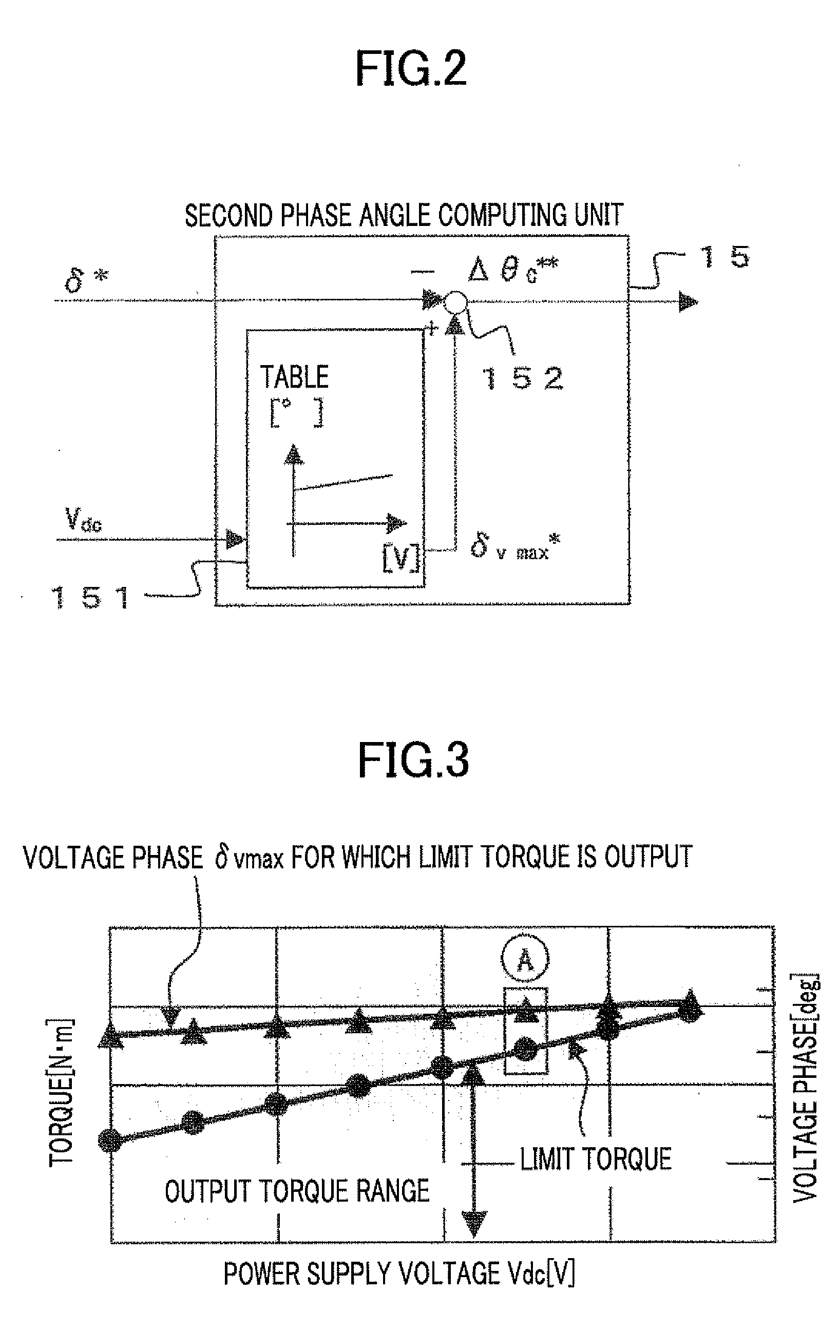
[0063]The voltage phase limit value δvmax* is set to the voltage phase δvmax for which the limit torque is output, corresponding to the computed frequency value ω1 with use of the table 171 of FIG. 8. The subtracter 152 subtracts the first voltage phase reference δ* from the voltage phase limit value δvmax*...

third embodiment

[0081]FIG. 12 shows a motor control system including a motor control apparatus according to a third embodiment of the present invention. Description of the blocks 1 to 5, 7 to 14, and 16 that are the same as in the first embodiment will be omitted. Although the second phase angle computing unit 15 of the first embodiment computes the second phase angle reference Δθc** based on the power supply voltage Vdc from the voltage detector 6 detecting the voltage of the DC power supply 1, the second phase angle computing unit 18 of the present embodiment computes the second phase angle reference Δθc** based on the d-axis current detected value Idc and the q-axis current detected value Iqc.

[0082]The detailed block diagram of the second phase angle computing unit 18 is shown in FIG. 13. The table 181 obtains the voltage phase limit value δvmax* based on the d-axis current detected value Idc and the q-axis current detected value Iqc. The subtracter 152 subtracts the first voltage phase referenc...


PUM


Abstract

A motor control apparatus which controls an output voltage reference for an inverter driving a permanent magnet synchronous motor based on d-axis and q-axis current references, d-axis and q-axis current detected values, and a computed frequency value. When a torque reference specifying torque greater than maximum torque that the motor can output is input, a limit value for a phase angle that is a deviation between a rotation phase reference of control and a rotation phase value of the motor is varied depending on a quantity of the predetermined state.

Description

CROSS REFERENCE TO RELATED APPLICATIONS[0001]This application claims the foreign priority benefit under Title 35, United States Code, §119(a)-(d) of Japanese Patent Application No. 2007-114971 filed on Apr. 25, 2007 in the Japan Patent Office, the disclosure of which is herein incorporated by reference in its entirety.BACKGROUND OF THE INVENTION[0002]1. Field of the Invention[0003]The present invention relates to a field weakening control apparatus for a permanent magnet motor and electric power steering using the same.[0004]2. Description of the Related Art[0005]As to a conventional technique related to phase control in a weakened field region, in JP 2005-110354A, there is described a method which gives a speed control unit an instruction to lower a current reference based on a voltage phase angle, thereby limiting the current reference to control a voltage phase.[0006]However, in the method of that Publication, variation in power supply voltage, variation in frequency, and variati...

Claims


Application Information

Patent Timeline
Patent Type & Authority Applications(United States)
IPC IPC(8): H02P27/08H02P27/04B62D6/00H02P21/00H02P21/22H02P23/16
CPCH02P21/0003H02P21/06
Inventor OL, KENTAROTOBARI, KAZUAKIIWAJI, YOSHITAKASASAKI, MITSUOMATSUMURA, TATSUO
Owner HITACHI ASTEMO LTD
Why Eureka
Try Eureka