Smart charging system for mobile vehicles and method of operating the same

a charging system and mobile technology, applied in secondary cell servicing/maintenance, electrochemical generators, batteries, etc., can solve the problems of cdma modems and cellular network communication being major drivers of system costs, hardware costs of evse themselves according to plugs, and cost simply being too high, so as to minimize overall costs and effective management of ev charging and grid loads

Active Publication Date: 2013-01-24
DELTA ELECTRONICS INC
View PDF8 Cites 85 Cited by
  • Summary
  • Abstract
  • Description
  • Claims
  • Application Information

AI Technical Summary

Benefits of technology

[0008]The need for smart-charging is intertwined with the issue of EVSE (charging apparatus) cost. The use of existing communication protocols, such as CDMA modems and cellular network communication is a major driver of costs at the systems level. If every EVSE was to employ cellular communications for grid-communication, costs will simply be too high. There is a need for an optimized communications strategy for smart EVSEs, which minimizes overall cost while providing effective management of EV charging and grid loads. A second related issue is the hardware cost of the EVSE itself According to Plug-In America, today's Level 2 (L2), UL Listed EVSEs cost between $1000 and $4500. This cost is itself a barrier to mass-market adoption of EVs; and this cost does not yet include grid-communication hardware and software. The addition of such hardware, and particularly multiple variants of communication protocols, such as CDMA, Wi-Fi, and so on, could be a driver of future costs. Although there exists not just one solution, notwithstanding an optimized low-cost route must be developed, considering the EVSE as a system, and taking advantage of low-cost technologies throughout the EVSE design.

Problems solved by technology

The use of existing communication protocols, such as CDMA modems and cellular network communication is a major driver of costs at the systems level.
If every EVSE was to employ cellular communications for grid-communication, costs will simply be too high.
A second related issue is the hardware cost of the EVSE itself According to Plug-In America, today's Level 2 (L2), UL Listed EVSEs cost between $1000 and $4500.
This cost is itself a barrier to mass-market adoption of EVs; and this cost does not yet include grid-communication hardware and software.

Method used


Image

  • Smart charging system for mobile vehicles and method of operating the same
  • Smart charging system for mobile vehicles and method of operating the same
  • Smart charging system for mobile vehicles and method of operating the same

Examples


first embodiment

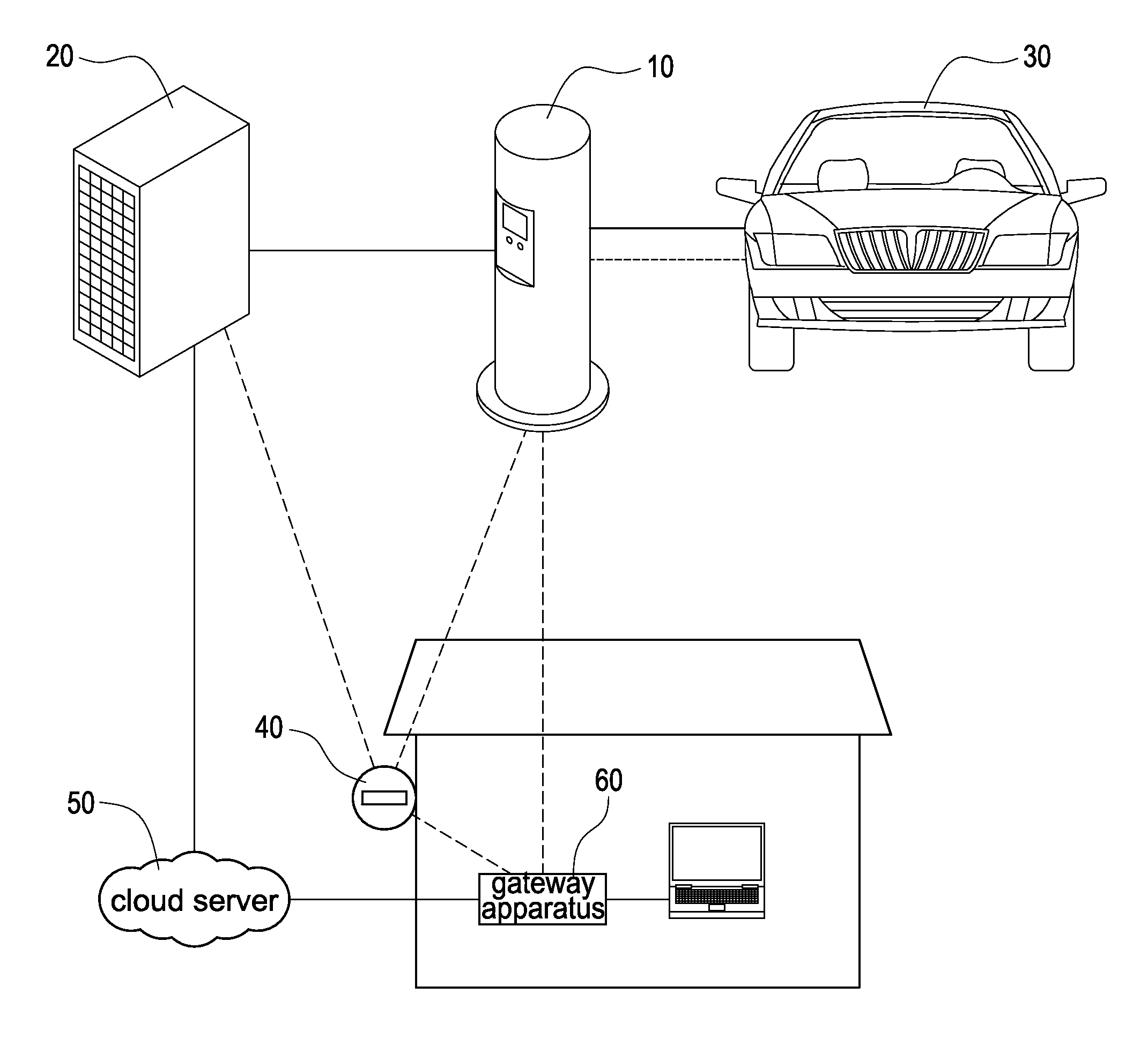
[0029]The detailed structures and operations of the smart charging system for mobile vehicles will be described hereinafter with a number of embodiments. Reference is made to FIG. 3 which is a schematic architecture block diagram of the smart charging system for mobile vehicles according to the present disclosure. This architecture possesses a number of cost saving advantages with simplicity, while still allowing for all of the required smart grid connectivity. As shown in FIG. 3, it is assumed that the advanced metering infrastructure (AMI) is provided and the gateway apparatus 60 is a home energy gateway (HEG). Hence, the user can select the preferred charging demand and then the gateway apparatus 60 and the charging apparatus 10 are used to exchange information.

[0030]To take full advantage of the offerings of the smart grid, and to allow for a universal interface to the vast array of utility companies, the gateway apparatus 60 is required. This allows connecting multiple smart en...

second embodiment

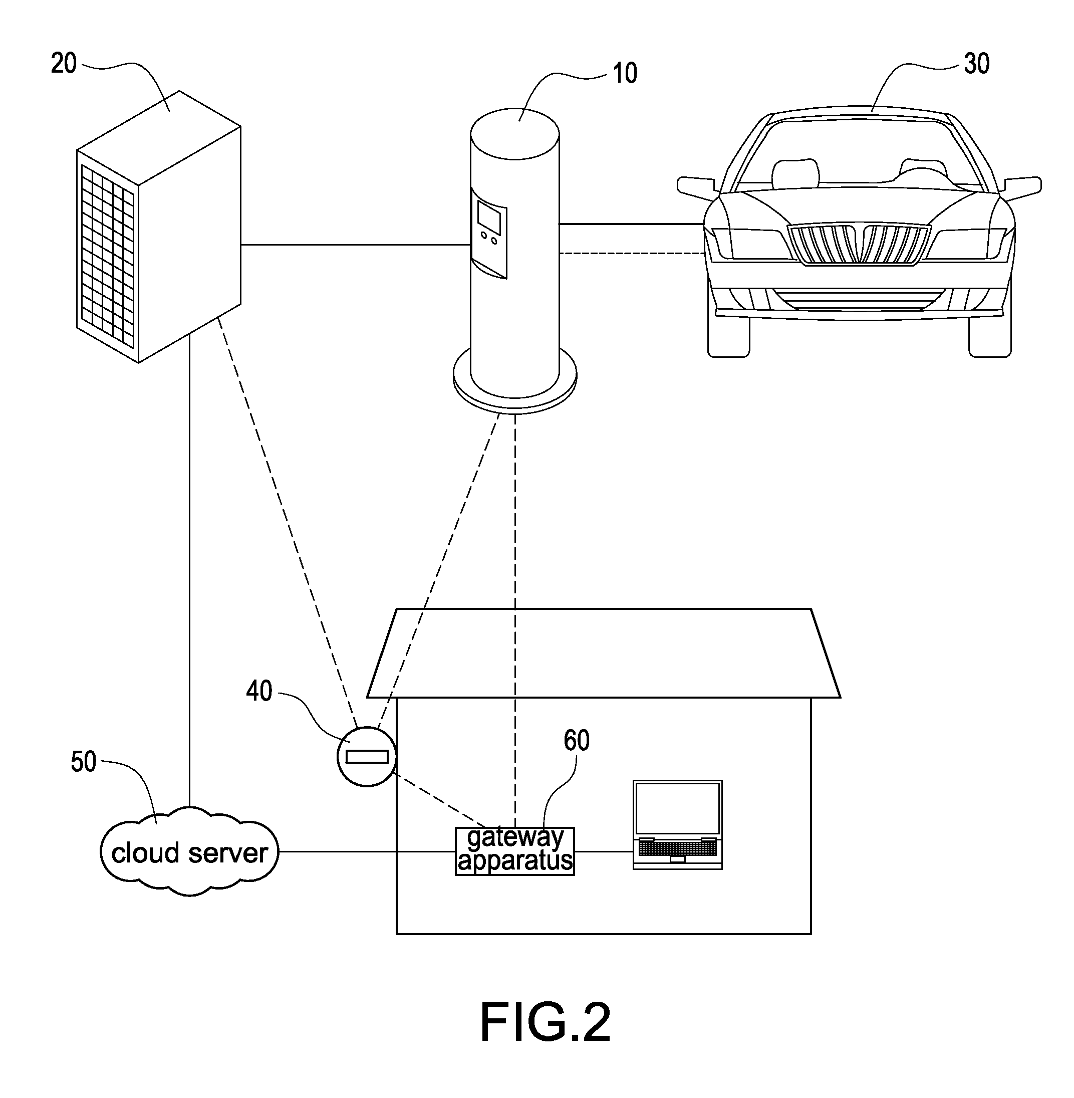
[0035]Reference is made to FIG. 4 which is a schematic architecture block diagram of the smart charging system for mobile vehicles according to the present disclosure. As shown in FIG. 4, all features that were described in the baseline architecture of FIG. 3 are still available, except for the interconnection of any household smart appliance. That is, this architecture considers a home without the Home Energy Gateway (HEG). To achieve this, Wi-Fi is provided as an optional inexpensive add-on available to consumers that choose not to have a gateway, allowing for the path of data transfer to the cloud server 50. In this case, the smart charging apparatus 10 automatically detects that the gateway is missing and automatically begins communicating directly to the AMI meter 40 using ZigBee communication. Therefore all instantaneous household power data is still available to the charging apparatus 10, even without the gateway. Especially, in this embodiment, the charging apparatus 10 is c...

third embodiment

[0036]Reference is made to FIG. 5 which is a schematic architecture block diagram of the smart charging system for mobile vehicles according to the present disclosure. In this embodiment, a household does not have an Advanced Metering Infrastructure (AMI) meter. This may be desirable in the short-term for some locations to overcome the challenges associated with replacing analog electrical meters that may currently exist at a residency, while still allowing the advantages of various billing and time-of-use implementations that can be configured for the electric vehicle charge time optimization. In this case, instantaneous household load information is not available and the charging apparatus 10 has to act into a limited control state. However, this situation can be improved by using the E2E communication of the smart charging apparatus 10 to gather loading information from the neighborhood sharing the same transformer. This allows the possibility of providing better control strategi...


PUM


Abstract

A smart charging system for mobile vehicles includes a charging apparatus, a meter, and a cloud server. The charging apparatus is connected between an electric grid and an electric vehicle. The charging apparatus is supplied by the electric grid and then provides power to supply the electric vehicle. The meter is operatively connected between the electric grid and the charging apparatus. The meter has a communication with the electric grid to obtain supplied power from the electric grid to the charging apparatus. The cloud server is operatively connected to the electric grid and further operatively connected to the charging apparatus via a gateway apparatus to receive power-supplying information of the electric grid and power-charging information of the electric vehicle. Further, the charging apparatus smartly charges the electric vehicle according to the power-supplying information and the power-charging information.

Description

CROSS REFERENCE TO RELATED APPLICATIONS[0001]This application claims priority of U.S. Provisional Application No. 61 / 509,685 filed on Jul. 20, 2011 under 35 U.S.C. §119(e), the entire contents of which are hereby incorporated by reference.BACKGROUND[0002]1. Technical Field[0003]The present disclosure relates generally to a smart charging system and a method of operating the same, and more particularly to a smart charging system for mobile vehicles and a method of operating the same.[0004]2. Description of Related Art[0005]The design and development of Electric Vehicle Supply Equipment (EVSE) has traditionally been performed without communication to the electrical grid. The focus to date has been on power protection, billing, and security functions. Although these functions provide the minimum required for EV charging, future EVSE must adapt to become more capable.[0006]Future EVSE will require grid connectivity for several reasons. Chief among these is the need to manage utility loa...

Claims


Application Information

Patent Timeline
Patent Type & Authority Applications(United States)
IPC IPC(8): H02J7/00
CPCH01M10/44Y02T90/121H04L67/12H04L67/02Y02T90/168Y04S30/12H04W12/08H02J7/0027B60L11/1844B60L11/1846Y02T10/7005Y02T90/16Y02T90/163Y02T90/169Y02T90/14Y02T90/128Y02T10/7055Y04S10/126Y04S30/14Y02E60/721H01M2220/20Y02T10/7072B60L53/63B60L53/65Y02E60/00Y02T10/70Y02T90/12Y02T90/167Y02E60/10H02J2310/48
Inventor WU, CHING-HORNGHU, JIAN-WEI
Owner DELTA ELECTRONICS INC
Why Eureka
Try Eureka