Heat management subsystems for LED lighting systems, LED lighting systems including heat management subsystems, and/or methods of making the same

Inactive Publication Date: 2013-01-24
GUARDIAN GLASS LLC
View PDF18 Cites 20 Cited by
  • Summary
  • Abstract
  • Description
  • Claims
  • Application Information

AI Technical Summary

Benefits of technology

[0013]In certain example embodiments, a remote phosphor plate may be used with a Fresnel lens to provide increased diffusion and/or homogenization of emitted light.
[0014]In certain example embodiments, a method of making a light fixture is proved. At least one cavity is formed in a glass substrate, the at least one cavity being tapered along a depth thereof so that the at least one cavity increases in diameter or distance from a first end thereof to a second end thereof. A reflective element is disposed on a surface of the at least one cavity. A light emitting diode (LED) is located at or proximate to the first end of each said cavity so as to enable the associated reflective element to reflect at least some light emitted from the respective LED, conserving étendue of the light from the respective LED.
[0015]In certain example embodiments, a method of making a light fixture is provided. At least one cavity is formed in a glass substrate, the at least one cavity being tapered along a depth thereof so that the at least one cavity increases in diameter or distance from a first end thereof to a second end thereof. A reflective element is disposed on a surface of the at least one cavity, the reflective element being adapted to reflect at least some light from a light source locatable at or proximate to the first end of each said cavity in order to conserve étendue of the light fro

Problems solved by technology

However, incandescent light bulbs are generally inefficient at generating light.
Despite these advantages, however, LEDs also suffer from certain disadvantages.
This difference may sometimes create barriers to achieving increased luminance on a target that is a given distance away from the plane of the light source.
In certain instances, the efficiency of an LED lig

Method used


Image

  • Heat management subsystems for LED lighting systems, LED lighting systems including heat management subsystems, and/or methods of making the same
  • Heat management subsystems for LED lighting systems, LED lighting systems including heat management subsystems, and/or methods of making the same
  • Heat management subsystems for LED lighting systems, LED lighting systems including heat management subsystems, and/or methods of making the same

Examples


Embodiment Construction

[0053]The following description is provided in relation to several example embodiments which may share common characteristics, features, etc. It is to be understood that one or more features of any one embodiment may be combinable with one or more features of other embodiments. In addition, single features or a combination of features may constitute an additional embodiment(s).

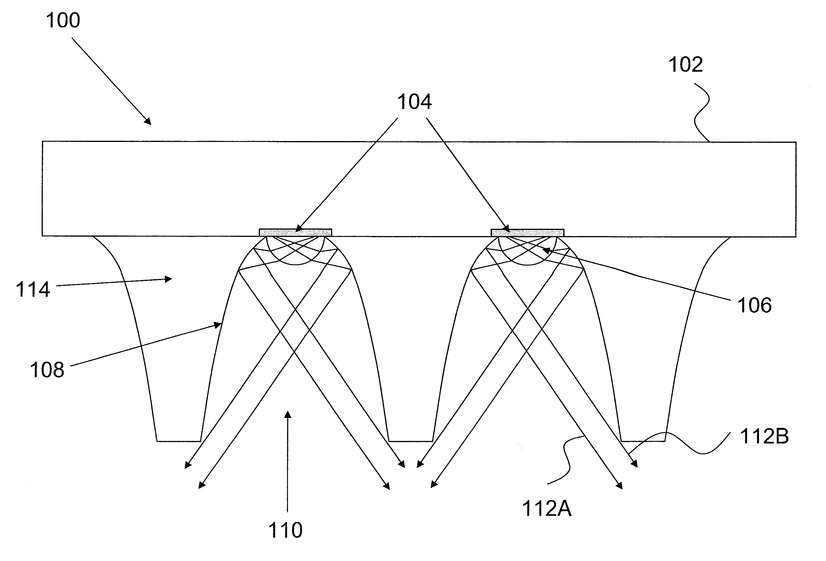
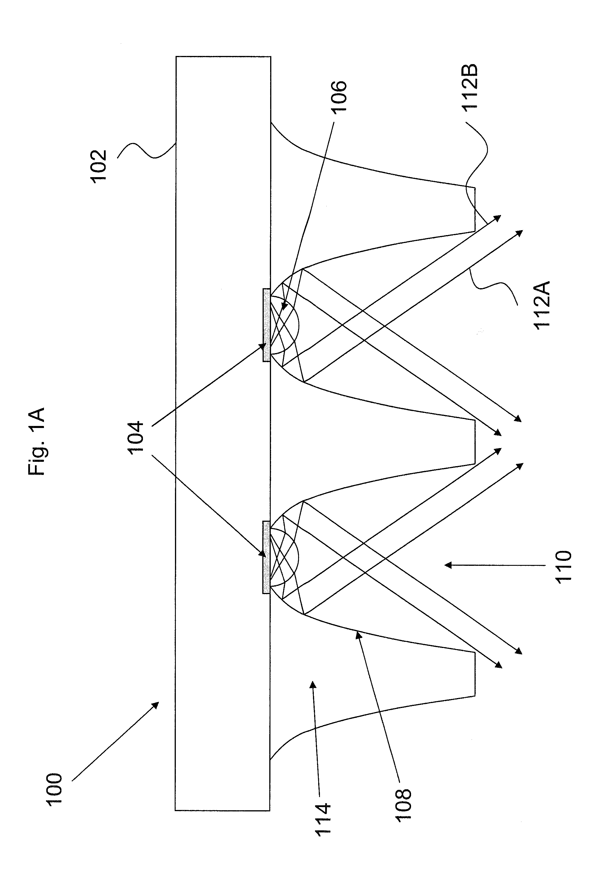
[0054]Certain example embodiments relate LED devices where the étendue is conserved and the emitted light is collimated. In certain example embodiments, a lighting apparatus may operate to prevent an excess “waste” of lighting and thereby increase the efficiency of the lighting apparatus.

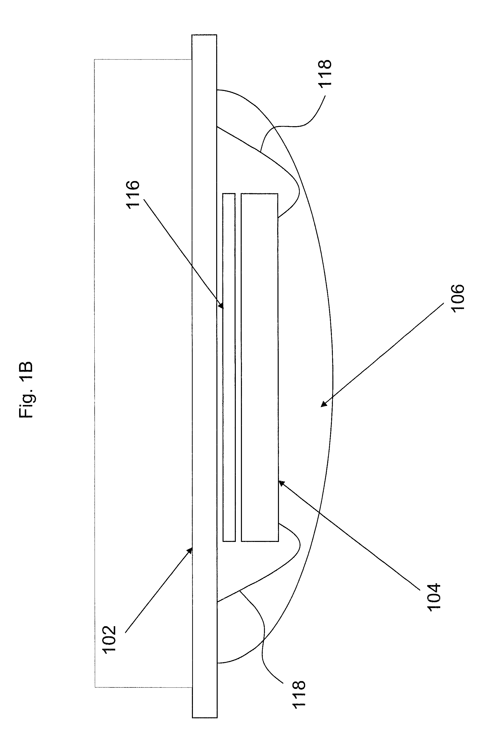
[0055]FIG. 1A is an illustrative cross-sectional view showing an exemplary lighting fixture according to certain example embodiments. In FIG. 1B, an enlarged cross-sectional view of a portion of luminaire 100 from FIG. 1A is shown. Light fixture (or luminaire) 100 includes a printed circuit board (PCB) 102 that is used to hous...


PUM

PropertyMeasurementUnit
Thicknessaaaaaaaaaa
Angleaaaaaaaaaa
Fractionaaaaaaaaaa

Abstract

Certain example embodiments relate to improved lighting systems and/or methods of making the same. In certain example embodiments, a lighting system includes a glass substrate with one or more apertures. An LED or other light source is disposed at one end of the aperture such that light from the LED directed through the aperture of the glass substrate exits the opposite end of the aperture. Inner surfaces of the aperture have a mirroring material such as silver to reflect the emitted light from the LED. In certain example embodiments, a remote phosphor article or layer is disposed opposite the LED at the other end of the aperture. In certain example embodiment, a lens is disposed in the aperture, between the remote phosphor article and the LED.

Description

[0001]Certain example embodiments of this invention relate to light emitting diode (LED) systems, and / or methods of making the same. More particularly, certain example embodiments relate to improved LED systems with increased light collection and conserved étendue for applications such as lighting luminaires (e.g., fixtures).BACKGROUND AND SUMMARY OF EXAMPLE EMBODIMENTS OF THE INVENTION[0002]For over a century, incandescent light bulbs have provided a majority of electrically-generated light. However, incandescent light bulbs are generally inefficient at generating light. Indeed, a majority of the power fed into an incandescent light bulb may be converted to heat rather than light.[0003]More recently, light emitting diodes (LEDs), or inorganic LEDs (ILEDs), have been developed. These relatively new light sources have continued development at a fairly rapid pace, with the applicability of certain semiconductor fabrication techniques leading to further increases in lumen output. Accor...

Claims


Application Information

Patent Timeline
IPC IPC(8): F21V9/16H05K13/00F25D17/00
CPCF21V29/20F21V23/0442F21Y2101/02F21V33/006F21S2/00Y10T29/49002F21V7/06F21V13/12F21V29/54F21V29/89F21V5/045F21V5/10F21V13/14F21V29/70F21Y2115/10
Inventor VEERASAMY, VIJAYEN S.ALVAREZ, JEMSSY
Owner GUARDIAN GLASS LLC
Why Eureka
Try Eureka