Video coding apparatus, video coding method and video coding program, and video decoding apparatus, video decoding method and video decoding program

Active Publication Date: 2013-01-24
COMCAST CABLE COMM LLC
View PDF5 Cites 16 Cited by
  • Summary
  • Abstract
  • Description
  • Claims
  • Application Information

AI Technical Summary

Benefits of technology

[0015]The present invention has been made considering these circumstances, and an object thereof is to provide a technology of suppressing an increase in the amoun

Problems solved by technology

However, since the above prediction of motion vectors cannot necessarily be obtained with high accuracy, a method for detecting a motion vector between reference images on both of the coding and decodin

Method used


Image

  • Video coding apparatus, video coding method and video coding program, and video decoding apparatus, video decoding method and video decoding program
  • Video coding apparatus, video coding method and video coding program, and video decoding apparatus, video decoding method and video decoding program
  • Video coding apparatus, video coding method and video coding program, and video decoding apparatus, video decoding method and video decoding program

Examples


first embodiment

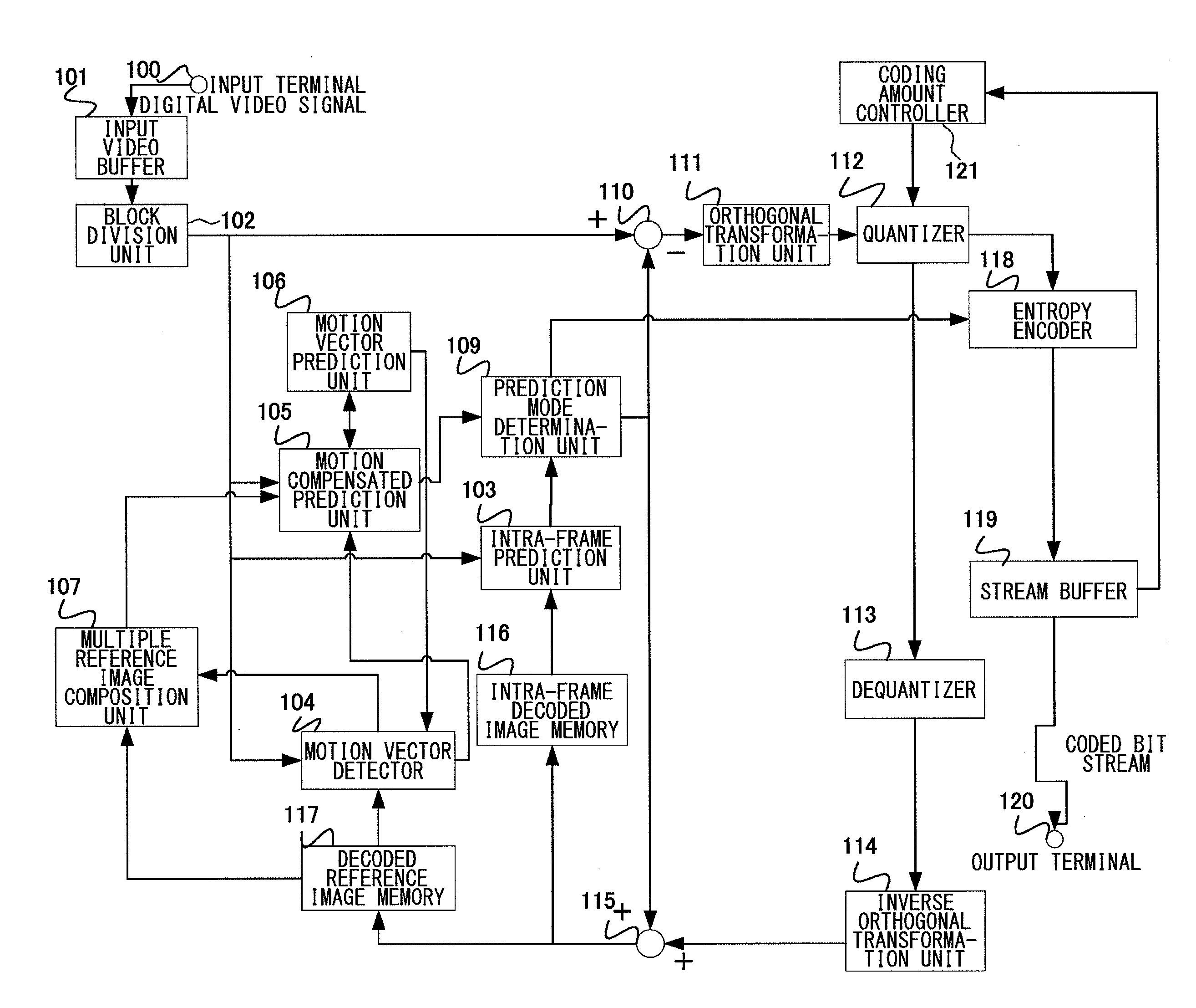
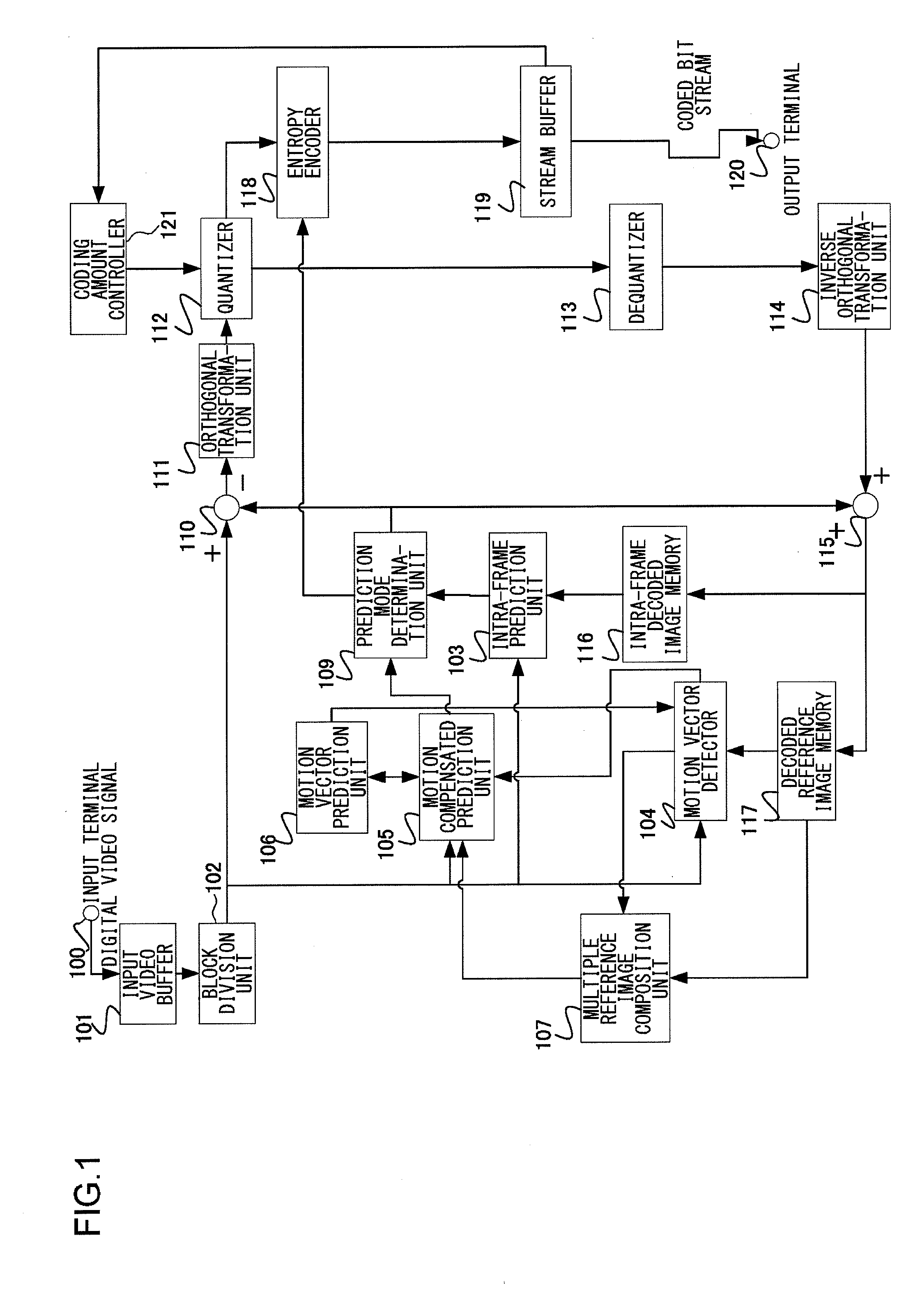
[0063]Firstly, a description will be given of a video coding apparatus of a first embodiment. FIG. 1 is a block diagram of the configuration of the video coding apparatus of the first embodiment.

[0064]As depicted in FIG. 1, the video coding apparatus of the first embodiment includes an input terminal 100, an input video buffer 101, a block division unit 102, an intra-frame prediction unit 103, a motion vector detector 104, a motion compensated prediction unit 105, a motion vector prediction unit 106, a multiple reference image composition unit 107, a prediction mode determination unit 109, a subtractor 110, an orthogonal transformation unit 111, a quantizer 112, a dequantizer 113, an inverse orthogonal transformation unit 114, an adder 115, an intra-frame decoded image memory 116, a decoded reference image memory 117, an entropy encoder 118, a stream buffer 119, an output terminal 120, and a coding amount controller 121.

[0065]The first embodiment of the present invention is characte...

second embodiment

[0112]Next, a description will be given of a second embodiment. The second embodiment takes a configuration where the accuracy of a motion vector to be used for the process of compositing reference images is decreased and a phase adjustment is made for a composited reference image at high accuracy. FIG. 6 is a block diagram of the configuration of a video coding apparatus of the second embodiment.

[0113]As depicted in FIG. 6, the video coding apparatus of the second embodiment includes an input terminal 100, an input video buffer 101, a block division unit 102, an intra-frame prediction unit 103, a motion vector detector 104, a motion compensated prediction unit 105, a motion vector prediction unit 106, a multiple reference image composition unit 107, a composite image motion compensated prediction unit 108, a prediction mode determination unit 109, a subtractor 110, an orthogonal transformation unit 111, a quantizer 112, a dequantizer 113, an inverse orthogonal transformation unit 1...

third embodiment

[0211]Next, a description will be given of a video coding apparatus and a video decoding apparatus in a third embodiment. In the third embodiment, the configurations of the video coding and decoding apparatuses take similar configurations to those of the second embodiment, and only the process of compositing reference images in the multiple reference image composition unit operates differently. Specifically, only the computation processes performed in the reference image composition units 404 and 1004, and S511 and S1114 of the flowcharts in the explanation of the second embodiment are different.

[0212]FIG. 17 depicts a conceptual diagram of the operation of the process of compositing reference images in the third embodiment, and the computation process will be described. In the second embodiment, the averaging to perform a uniform averaging process is performed on all pixel values in a block in the composition process. However, in composition process of the third embodiment, an erro...


PUM


Abstract

A motion vector detector detects a motion vector from a first reference image for a coding target block. A multiple reference image composition unit creates a composite reference block that a first reference block extracted from the first reference image using the motion vector has been composited with a predetermined region of at least one of other reference images. Setting the composite reference block as a prediction block, an entropy encoder encodes a prediction difference block that the prediction block has been subtracted from the coding target block.

Description

BACKGROUND OF THE INVENTION[0001]1. Field of the Invention[0002]The present invention relates to a coding technology and a decoding technology of a video signal.[0003]2. Description of the Related Art[0004]In recent years, a service to distribute digitized image and audio contents via a broadcast wave such as a satellite and a ground wave, and a network has been realized, and a highly-efficient coding technology for efficiently recording and transmitting contents having a massive amount of information is being required. Used as the highly-efficient video coding is a method for compressing information using a correlation between spatially adjacent pixels in the same frame of a video signal, and correlations between temporally adjacent frames and fields, as represented by MPEG-4 AVC.[0005]In MPEG-4 AVC, used as compression using a temporal correlation is motion compensated prediction to use a locally decoded image of an already-coded frame as a reference image for a target image being...

Claims


Application Information

Patent Timeline
IPC IPC(8): H04N7/32
CPCH04N19/51H04N19/52
Inventor UEDA, MOTOHARUSAKAZUME, SATORUFUKUSHIMA, SHIGERUKUMAKURA, TORU
Owner COMCAST CABLE COMM LLC
Why Eureka
Try Eureka