Electronic sphygmomanometer for measuring blood pressure based on arterial volume change

a technology of arterial volume change and sphygmomanometer, which is applied in the field of sphygmomanometer, can solve the problems of difficult adjustment of servo gain, inability to completely eliminate blood pressure measurement error, etc., and achieve the effect of measuring accurately

Active Publication Date: 2013-01-24
OMRON HEALTHCARE CO LTD
View PDF4 Cites 18 Cited by
  • Summary
  • Abstract
  • Description
  • Claims
  • Application Information

AI Technical Summary

Benefits of technology

[0019]Accordingly, blood pressure can be measured accurately based on the change in arterial volume, without giving rise to an i

Problems solved by technology

However, because a characteristic of PID control is that oscillations occur in the response of the cuff pressure control system as a result of raising the servo gain, blood pressure m

Method used


Image

  • Electronic sphygmomanometer for measuring blood pressure based on arterial volume change
  • Electronic sphygmomanometer for measuring blood pressure based on arterial volume change
  • Electronic sphygmomanometer for measuring blood pressure based on arterial volume change

Examples


Embodiment Construction

[0030]An embodiment of the present invention will be described in detail, with reference to the drawings. Note that the same reference signs are given to portions that are the same or equivalent in the drawings, and description thereof will not be repeated.

External Appearance

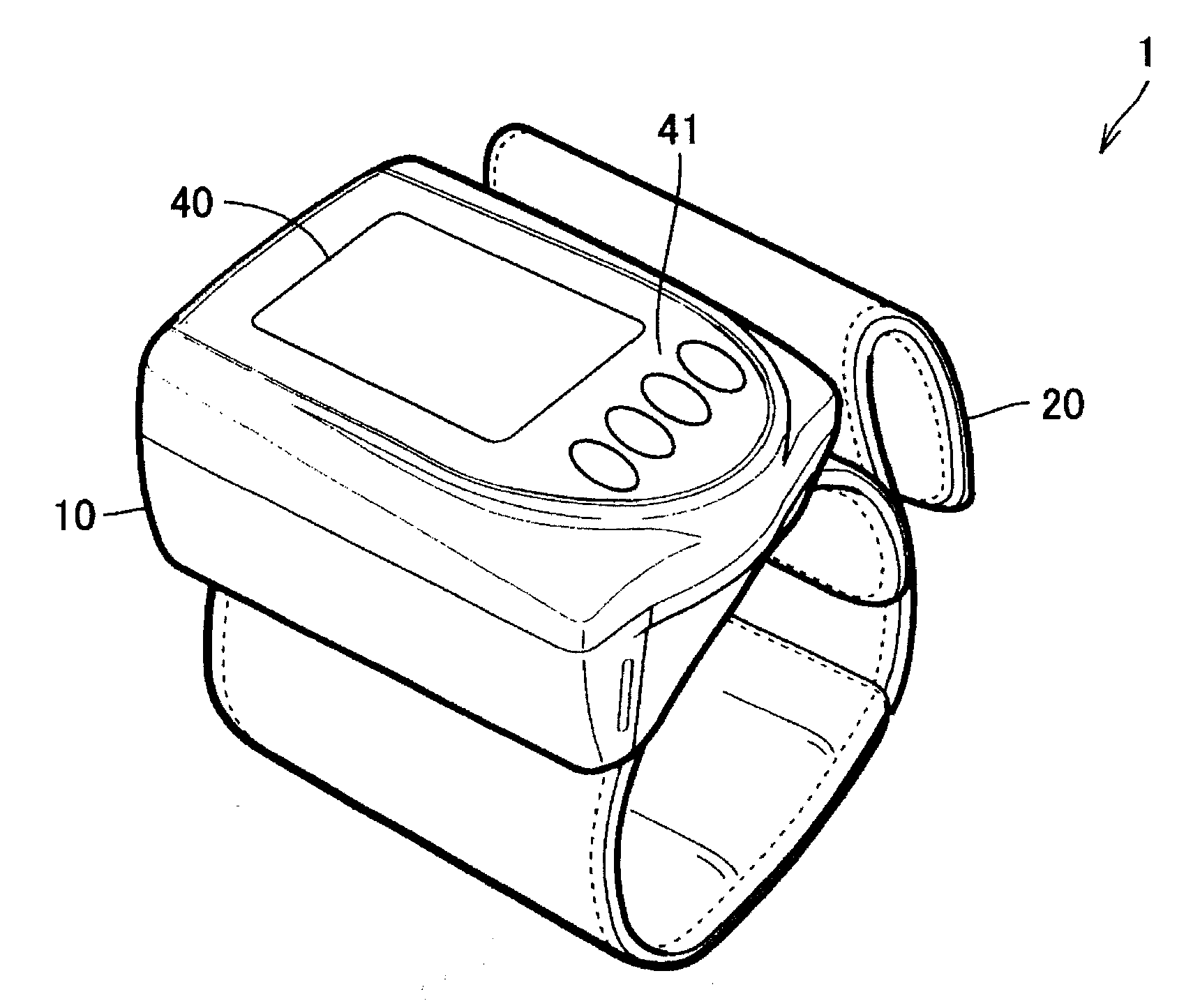
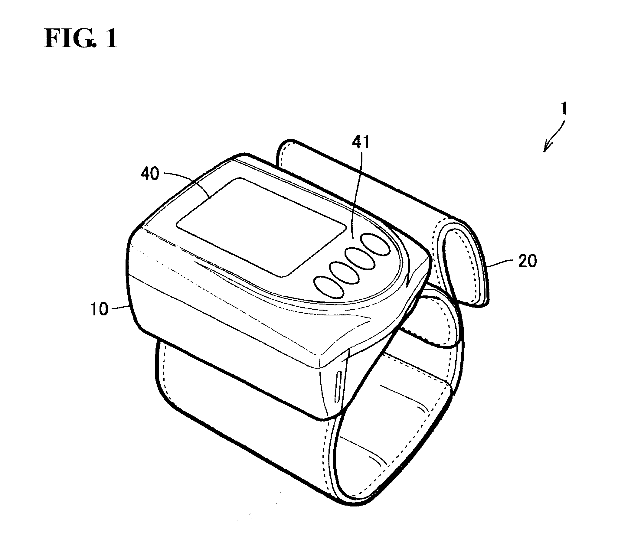
[0031]FIG. 1 is an external perspective view of an electronic sphygmomanometer 1 according to an embodiment of the present invention.

[0032]Referring to FIG. 1, the electronic sphygmomanometer 1 is provided with a main body unit 10 and a cuff 20 that is capable of being wrapped around a prescribed measurement site of the person being measured. The main body unit 10 is attached to the cuff 20. A display unit 40 is constituted by liquid crystal, for example, and an operation unit 41 that is operated in order to receive instructions from a user (e.g., person being measured) are disposed on the surface of the main body unit 10. The operation unit 41 includes a plurality of switches.

[0033]In the present embodiment, th...


PUM


Abstract

Every pulse wave, a constant volume control unit performs servo control while updating a servo gain such that a difference between an arterial volume shown by an arterial volume signal that is detected by an arterial volume detection circuit and a control target value of the servo control is less than a control deviation at which a rate of change of the arterial volume relative to a change in cuff pressure is deemed to be constant. Because the control deviation is the difference between the arterial volume shown by the arterial volume signal and the control target value, a blood pressure decision unit decides, as a blood pressure, the cuff pressure sequentially detected in a period during which servo control is performed, by correcting the cuff pressure using the control deviation and the rate of change deemed to be constant.

Description

TECHNICAL FIELD [0001]This invention relates to an electronic sphygmomanometer, and more particularly to an electronic sphygmomanometer for continuously measuring blood pressure every heartbeat while detecting change in arterial volume.BACKGROUND ART [0002]With a conventional electronic sphygmomanometer, an arm band (cuff) is wrapped around a measurement site, the pressure inside the cuff (cuff pressure) is increased to greater than the highest blood pressure, and a pulse produced by an artery is detected with a pressure sensor via the cuff in a subsequent process of gradually reducing the cuff pressure, with the highest blood pressure and the lowest blood pressure being decided utilizing the cuff pressure and the magnitude of the pulse (pulse wave amplitude) at that time (oscillometric method). In contrast, a sphygmomanometer employing a volume compensation method that is configured to continuously measure blood pressure every heartbeat in a noninvasive manner has been developed (P...

Claims


Application Information

Patent Timeline
IPC IPC(8): A61B5/0225A61B5/025
CPCA61B5/02116A61B5/7239A61B5/02438
Inventor TOKKO, YOSHIHIDESAWANOI, YUKIYA
Owner OMRON HEALTHCARE CO LTD
Why Eureka
Try Eureka