Apparatus for and method of controlling internal combustion engine

Inactive Publication Date: 2013-01-24
HITACHI AUTOMOTIVE SYST LTD
View PDF1 Cites 11 Cited by
  • Summary
  • Abstract
  • Description
  • Claims
  • Application Information

AI Technical Summary

Benefits of technology

[0008]Therefore, it is an object of an aspect of the present invention to provide an apparatus for and method of controlling an internal combu

Problems solved by technology

This results in interrupting the introduction of intake air through the first intake port in the middle of the intake stroke.
As a result, the gas flow in the combustion chamber is weakened, causing a problem that mixin

Method used


Image

  • Apparatus for and method of controlling internal combustion engine
  • Apparatus for and method of controlling internal combustion engine
  • Apparatus for and method of controlling internal combustion engine

Examples


Example

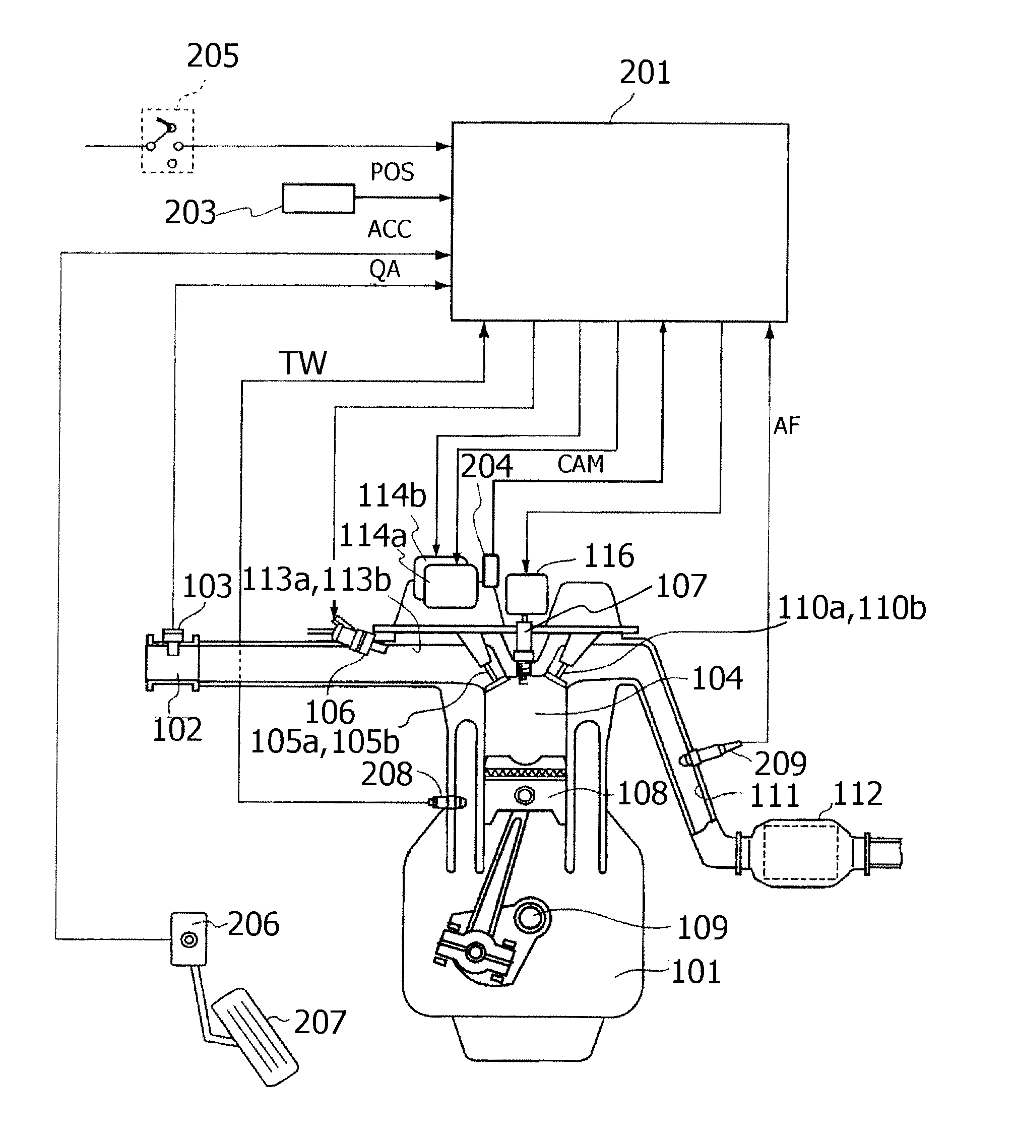
[0030]FIG. 1 is a diagram illustrating a vehicle engine system to which a control apparatus according to the present invention is applied.

[0031]An engine 101 illustrated in FIG. 1 is a serial multi-cylinder internal combustion engine, however, it may be a V type or horizontal-opposed engine.

[0032]In an intake pipe 102 for introducing air into each cylinder of engine 101, an intake air amount sensor 103 is provided to detect an intake air amount QA of engine 101. As the intake air amount sensor 103, for example, a hot-wire flowmeter for detecting the mass flow rate of intake air or the like may be used.

[0033]In each combustion chamber 104, a first intake valve 105a and a second intake valve 105b for opening and closing an intake port of combustion chamber 104 are provided. Furthermore, a fuel injection valve 106 is provided for each cylinder in an intake port portion of intake pipe 102 upstream of intake valves 105a and 105b.

[0034]Fuel injected from fuel injection valve 106 into com...


PUM


Abstract

A control apparatus for an internal combustion engine where the inside of a combustion chamber is divided into a layer of internal EGR gas and a combustible layer to perform stratified combustion. In a port-injected engine equipped with first and second intake valves, the opening timing of the first intake valve is set before a top dead center (TDC) and the opening timing of the second intake valve is set after the TDC, and the closing timings of the first intake valve and the second intake valve are set after a bottom dead center. Then, fuel injection toward the first intake valve is started after the EGR gas, which was blown back to the intake port upstream of the first intake valve, is drawn into the combustion chamber after the top dead center.

Description

BACKGROUND OF THE INVENTION[0001]1. Field of the Invention[0002]The present invention relates to a control apparatus and a control method for an internal combustion engine that divides the inside of a combustion chamber into a layer of internal EGR gas and a combustible layer to perform stratified combustion.[0003]2. Description of Related Art[0004]Conventionally, as disclosed in Japanese Laid-Open Patent Publication No. 2008-255866, there has been an internal combustion engine that divides the inside of a combustion chamber into a layer of internal EGR gas and a combustible layer to ignite the combustible layer to thereby perform stratified combustion.[0005]In the internal combustion engine, internal EGR gas is introduced into a first intake port located upstream of a first intake valve in an exhaust stroke. Then, in an intake stroke, the internal EGR gas in the first intake port is introduced into a combustion chamber through the first intake valve and fresh air in a second intake...

Claims


Application Information

Patent Timeline
IPC IPC(8): F02D41/26F02D41/34
CPCF02D41/30Y02T10/47F02D41/3023F02M35/10177F02M35/1085F02B17/00F02M25/0752F02D13/0234F02D13/0257F02D41/0062F02D2041/001Y02T10/18Y02T10/146Y02T10/12Y02T10/14F02D41/006F02M26/01Y02T10/40
Inventor MURAI, ATSUSHI
Owner HITACHI AUTOMOTIVE SYST LTD
Why Eureka
Try Eureka