Seawater desalination system and energy exchange chamber

Active Publication Date: 2012-03-15
EBARA CORP
View PDF0 Cites 19 Cited by
  • Summary
  • Abstract
  • Description
  • Claims
  • Application Information

AI Technical Summary

Benefits of technology

[0072]According to the present invention, the following effects can be achieved.
[0073]1) Because of no-piston configuration in the chamber, a problem of wear of a sliding member can be solved and excessive machining accuracy of the chamber and excessively elongated machining of the chamber are not required. Therefore, the manufacturing cost of the chamber can be reduced.
[0074]2) Mixing of concentrated seawater and seawater in the chamber can be suppressed irrespective of the no-piston configuration in the chamber, and the seawater can be pressurized by the concentrated seawater while the interface between the concentrated seawater and the seawater is maintained.
[0075]3) Because mixing of the concentrated seawater and the seawater in the chamber due to turbulent flow diffusion can be suppressed and the seawater having a high salt content is not delivered to the reverse-osmo

Problems solved by technology

The largest operational cost (electric expenses) in the seawater desalination system is energy cost for pressurizing the pretreated seawater up to such a pressure as to overcome the osmotic pressure, i.e. up to the reverse-smosis pressure.
That is, the operational cost of the seawater desalination system depends heavily on pressurizing energy of the seawater by the high-pressure pump.
Specifically, more than half of the electric expe

Method used


Image

  • Seawater desalination system and energy exchange chamber
  • Seawater desalination system and energy exchange chamber
  • Seawater desalination system and energy exchange chamber

Examples


Example

[0105]A seawater desalination system according to preferred embodiments of the present invention will be described in detail below with reference to FIGS. 1 through 24. Like or corresponding parts are denoted by like or corresponding reference numerals in FIGS. 1 through 24 and will not be described below repetitively.

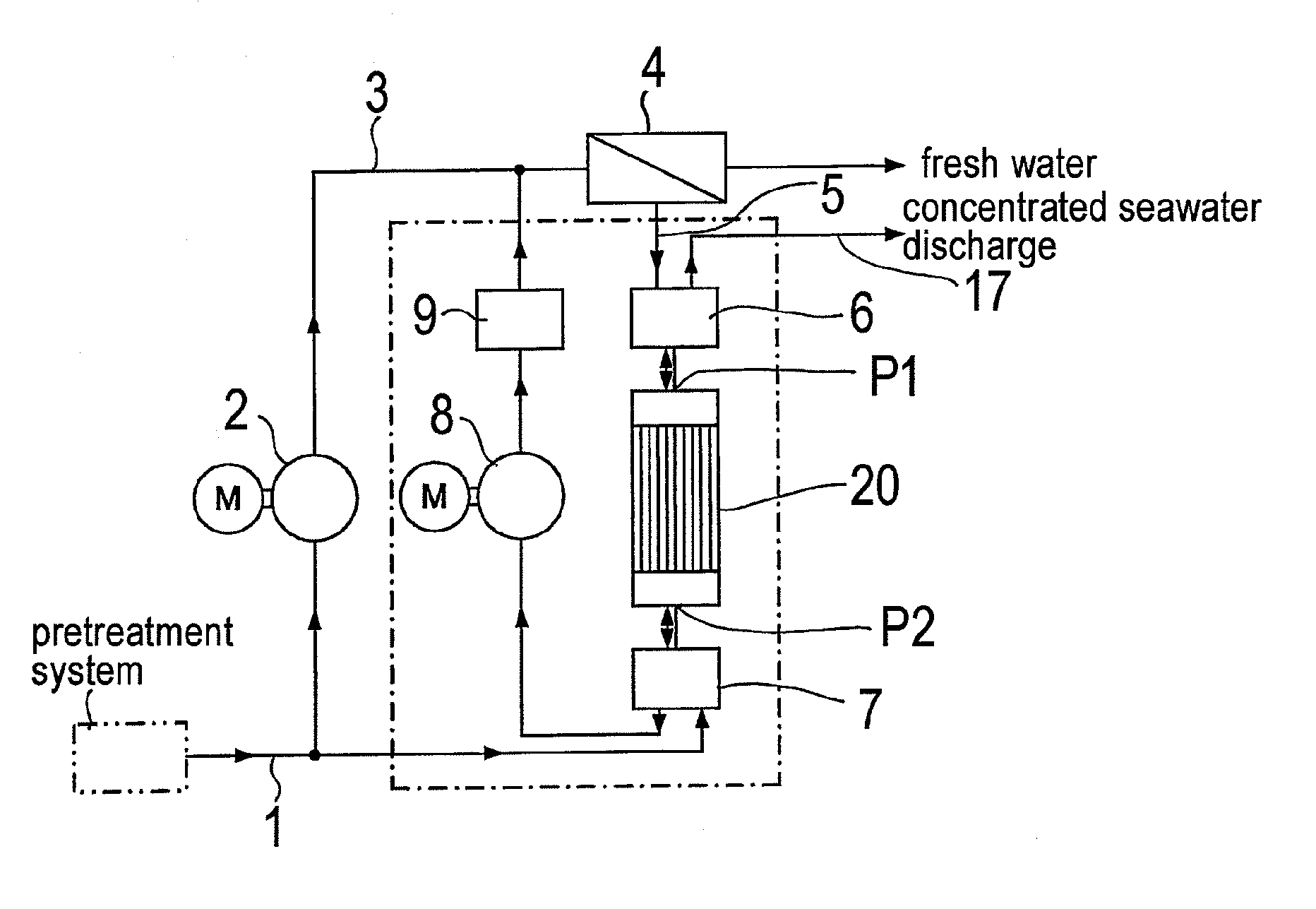
[0106]FIG. 1 is a schematic view showing a configuration example of a seawater desalination system according to the present invention. As shown in FIG. 1, seawater pumped into the seawater desalination system by an intake pump (not shown) is processed to have certain water qualities by a pretreatment system, and then the pretreated seawater is delivered via a seawater supply line 1 into a high-pressure pump 2 that is directly coupled to a motor M. The seawater which has been pressurized by the high-pressure pump 2 is supplied via a discharge line 3 to a reverse-osmosis membrane-separation apparatus 4. The reverse-osmosis membrane-separation apparatus 4 separates the se...


PUM

PropertyMeasurementUnit
Diameteraaaaaaaaaa
Energyaaaaaaaaaa

Abstract

A seawater desalination system which can solve a problem of wear of a sliding member and can suppress mixing of concentrated seawater and seawater by making an energy exchange chamber no-piston configuration is provided.
In a seawater desalination system for producing fresh water from seawater by passing the seawater pressurized by a pump through a reverse-osmosis membrane-separation apparatus (4) to separate the seawater into fresh water and concentrated seawater, an energy exchange chamber (20) for utilizing pressure energy of the concentrated seawater discharged from the reverse-osmosis membrane-separation apparatus (3) as energy for pressurizing part of the seawater is provided. The energy exchange chamber includes a concentrated seawater port (P1) for introducing and discharging the concentrated seawater, a seawater port (P2) for introducing and discharging the seawater, and a plurality of partitioned fluid passages (R) provided in the chamber to allow the concentrated seawater port (P1) and the seawater port (P2) to communicate with each other.

Description

TECHNICAL FIELD[0001]The present invention relates to an energy exchange chamber (pressure exchange chamber) which is preferably used in a seawater desalination system (seawater desalination plant) for desalinating seawater by removing salinity from the seawater.BACKGROUND ART[0002]Conventionally, as a system for desalinating seawater, there has been known a seawater desalination system in which seawater passes through a reverse-osmosis membrane-separation apparatus to remove salinity from the seawater. In the seawater desalination system, the intake seawater is processed to have certain water qualities by a pretreatment system, and the pretreated seawater is delivered into the reverse-osmosis membrane-separation apparatus under pressure by a high-pressure pump. Part of the high-pressure seawater in the reverse-osmosis membrane-separation apparatus passes through a reverse-osmosis membrane against the reverse-osmosis pressure and is desalinated, and fresh water (permeate or desalted...

Claims


Application Information

Patent Timeline
IPC IPC(8): B01D61/06C02F1/44B01D61/02
CPCB01D61/025B01D61/06C02F2303/10C02F2201/004C02F1/441B01D2313/246B01D63/02B01D61/10B01D61/08Y02W10/30Y02A20/131
Inventor TAKAHASHI, TAMAMISHINODA, MASAOEGUCHI, MASATOGOTO, MASANORI
Owner EBARA CORP
Why Eureka
Try Eureka