A plenoptic mirror frequency suppression mixing device and method

An optical mirror and frequency mixing technology, which is applied in electrical components, electromagnetic wave transmission systems, transmission systems, etc., can solve the problems of difficult integration, complex systems, and difficult components, and achieve the effect of easy integrated integration and simplified system structure.

Active Publication Date: 2022-04-05
EAST CHINA NORMAL UNIV
View PDF5 Cites 0 Cited by
  • Summary
  • Abstract
  • Description
  • Claims
  • Application Information

AI Technical Summary

Problems solved by technology

The disadvantage of this is that the system is relatively complicated, and a pair of photodetectors are required to generate two intermediate frequency signals; more importantly, the system requires a 90° electrical mixer, which is difficult to integrate with other optoelectronic devices, making the existing Image frequency rejection mixing technology based on microwave photonic technology is difficult to integrate

Method used


Image

  • A plenoptic mirror frequency suppression mixing device and method
  • A plenoptic mirror frequency suppression mixing device and method
  • A plenoptic mirror frequency suppression mixing device and method

Examples


Embodiment

[0031] The concrete realization process of this embodiment is:

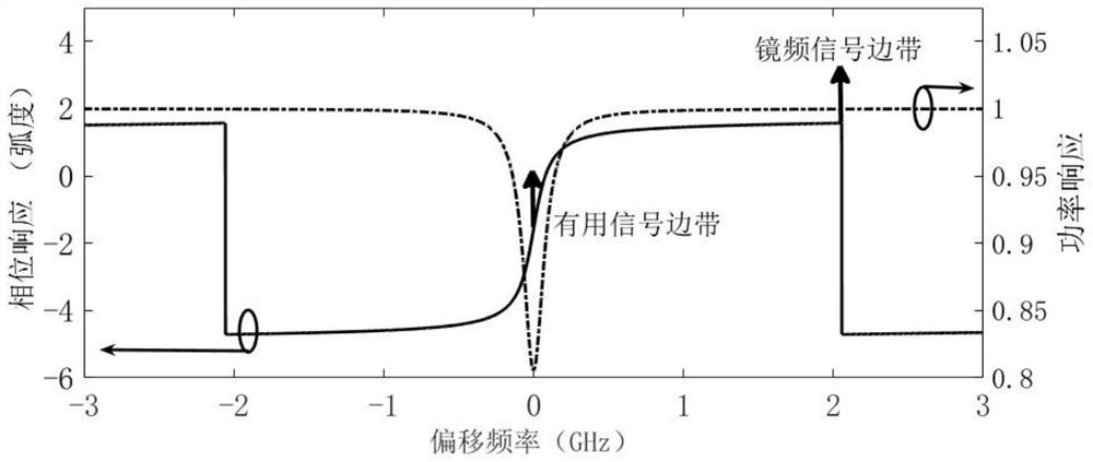
[0032] Step 1. Design the phase-shifted fiber Bragg grating 7 and take its effective refractive index n eff =1.45, the refractive index change value △n=4×10 -4 , the corresponding Bragg wavelength is 1550nm, the total length is 9cm, and the length ratio of the two sub-fiber gratings before and after the phase shift position is 3:2. Its reflected power spectrum and phase spectrum are as figure 2 As shown, it can be seen that there is a small sag in the power spectrum, the phase response corresponding to the central frequency of the sag is -90 degrees, and the phase response at 2.056 GHz away from this point is 90 degrees. If the sidebands generated by the useful signal and the mirror frequency signal correspond to these two positions, a phase difference of 180 degrees can be obtained between the two, and the optical domain Hilbert transform can be realized to separate the two.

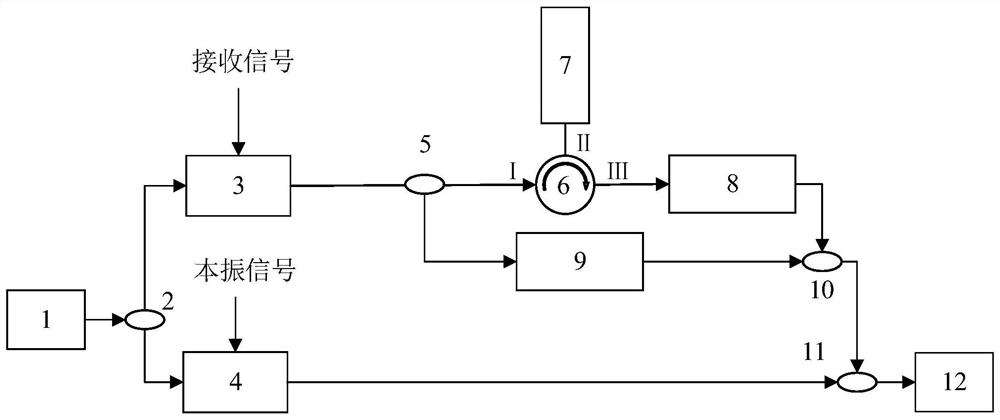
[0033] Step 2: The light source...


PUM


Abstract

The invention relates to an all-optical mirror frequency suppression mixing device and method. The device comprises a continuous wave laser, first and second suppressed carrier SSB modulators, first and second optical power dividers, optical circulators, Phase-shift fiber Bragg grating, optical phase shifter, tunable optical attenuator, first and second optical couplers, photodetector; the method is to modulate the received signal including the useful signal and the image frequency signal to generate a single suppressed carrier wave The sideband modulation signal is input into a specially designed phase-shift fiber Bragg grating and optical phase shifter to realize the Hilbert transform of the optical domain, and then coupled with the optical signal without the Hilbert transform of the optical domain to realize the image frequency interference signal. Optical domain suppression: After the optical signal with the image frequency interference is suppressed and the optical sideband signal generated by the local oscillator signal, the beat frequency can be achieved, and the image frequency suppression mixing can be realized. The invention realizes the suppression of image frequency interference in the optical domain for the first time, the adopted device is easy to be integrated, and has a good application prospect.

Description

technical field [0001] The invention belongs to the technical field of microwave signal processing, and in particular relates to a plenoptic mirror frequency suppression mixing device and method. Background technique [0002] Frequency conversion, that is, frequency mixing, is a necessary functional module in systems such as wireless communication systems, radar systems, and telemetry and remote control systems. Through frequency mixing, the high-frequency signal can be converted into a medium-low frequency signal, which is convenient for subsequent sampling, processing and transmission of the signal. The role of the mixer is very important, and its performance directly affects the performance of the entire system. [0003] Modern communication systems widely use superheterodyne receivers. If the frequency of the local oscillator signal is f LO , the frequency is f RF A useful radio frequency (RF) signal with another frequency f IM The image frequency signal satisfies f ...

Claims


Application Information

Patent Timeline
Patent Type & Authority Patents(China)
IPC IPC(8): H04B10/61
CPCH04B10/6151H04B10/6163
Inventor 陈阳陈煜
Owner EAST CHINA NORMAL UNIV
Why Eureka
Try Eureka