Water Self-Shutoff Tubular

a technology of self-shutoff and tubular water, which is applied in the direction of water supply installation, gas/liquid distribution and storage, and fluid removal. it can solve the problems of underground blowout, weak points that are even more susceptible to leakage, and leakage of casings, so as to improve the recovery of hydrocarbons, improve the recovery effect, and facilitate operation.

Active Publication Date: 2013-01-31
SAUDI ARABIAN OIL CO
View PDF11 Cites 5 Cited by
  • Summary
  • Abstract
  • Description
  • Claims
  • Application Information

AI Technical Summary

Benefits of technology

[0008]Additional benefits of the embodiments of the present application are that they provide maintenance free and easier to operate solutions than current prior art. Most of the manufacturing of the tubular is completed in a more controlled environment at the surface, customized to meet specific well conditions. And in providing a venue for cost savings in addition to improving recovery of hydrocarbons, it uses easily obtainable, natural soil resources which are in abundance, such as local sands and clays.

Problems solved by technology

Casing leaks may be caused by, among other things, corrosion, pitting and cracking due to acidic or caustic water from the formation or reservoir.
Wear from running the casing into the well, particularly for deviated wells, can lead to weak points that are even more susceptible to leaking caused by corrosive water from the formation.
Casing leaks may allow high pressure fluids and gasses and unwanted chemicals to enter the annulus and in extreme cases, can lead to underground blowouts.
This in turn potentially limits the production and the services (such as maintenance) of the wellbore.
Another issue facing oil and gas well producers is the management and control of water production.
Ingress of water into the wellbore will increase the cost of production because the water will then have to be separated from the oil and gas at the surface.
However these methodologies are expensive in terms of initial costs as well as in terms of time and costs spent on maintenance and repairs.

Method used


Image

  • Water Self-Shutoff Tubular
  • Water Self-Shutoff Tubular
  • Water Self-Shutoff Tubular

Examples


Embodiment Construction

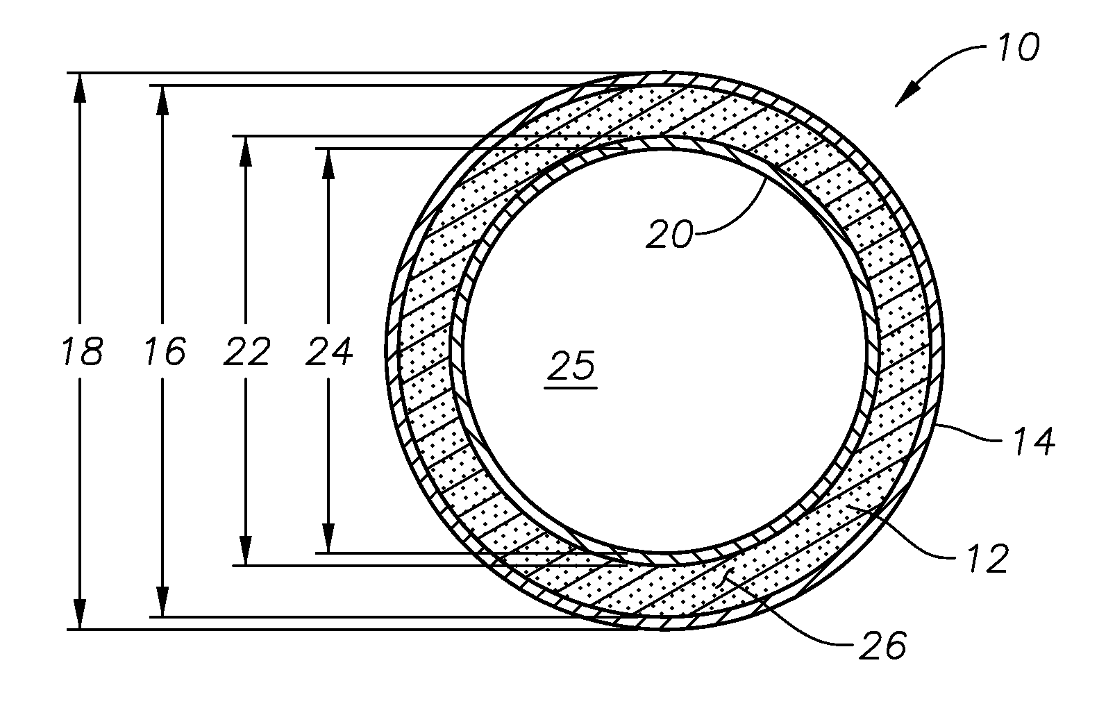
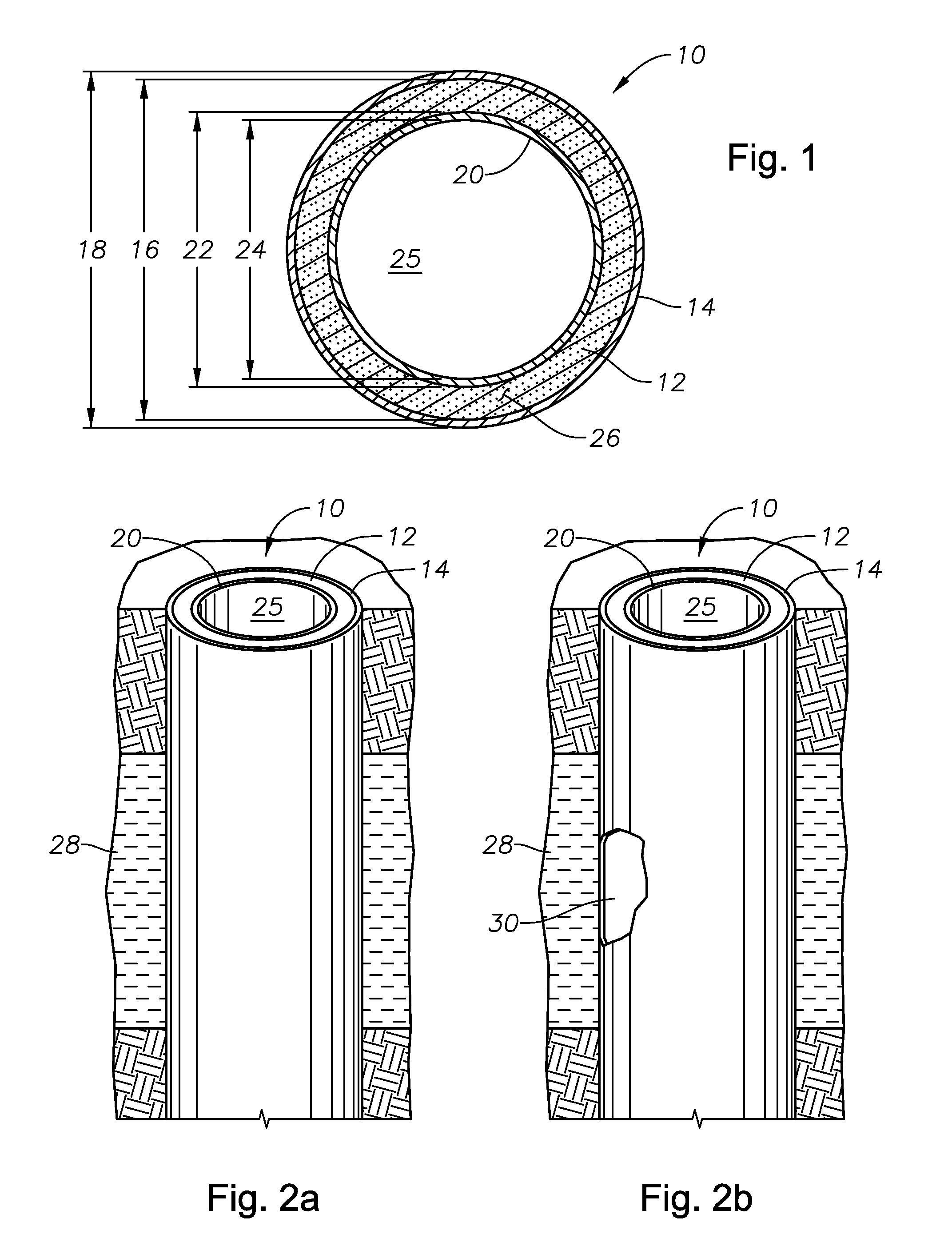
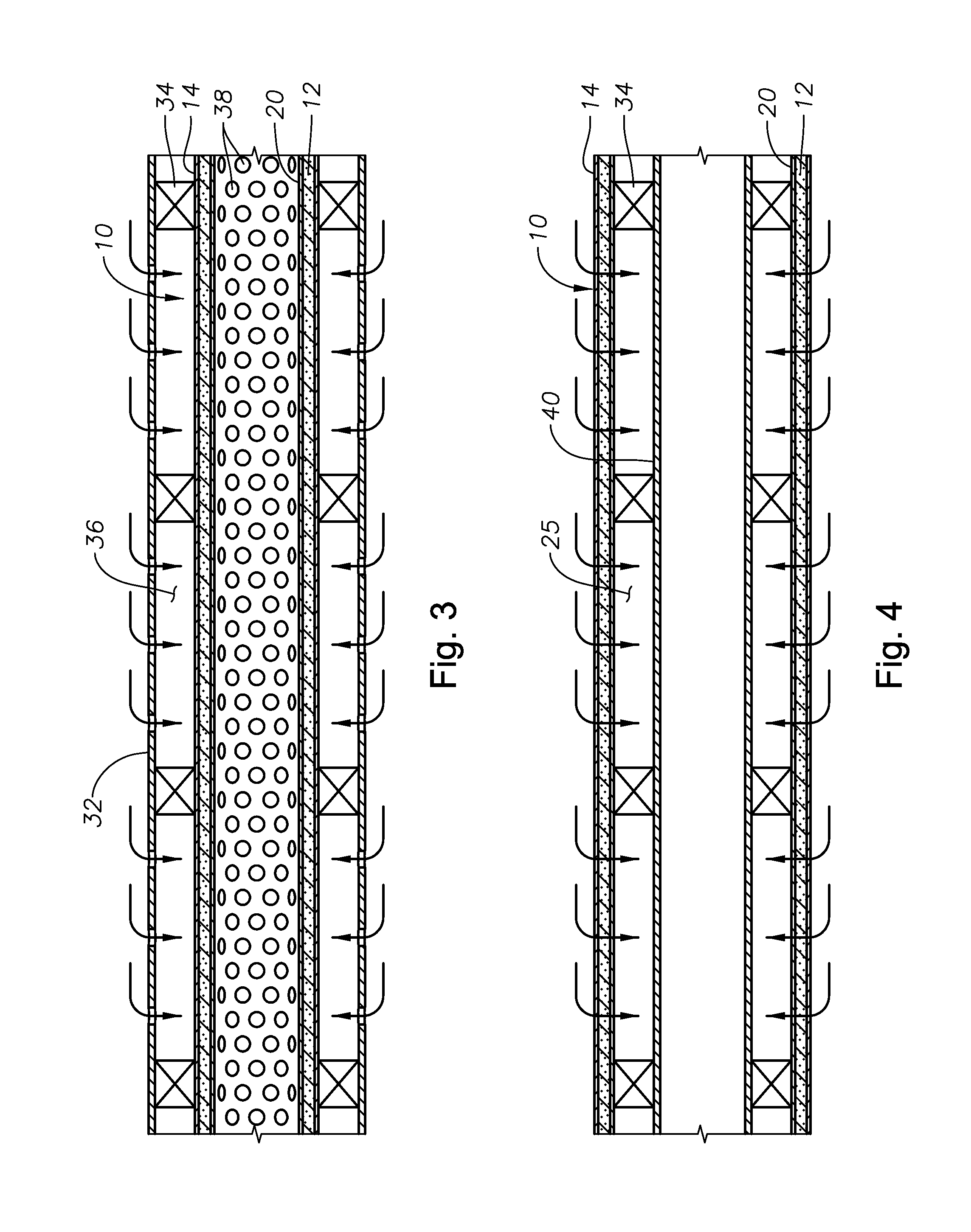
[0025]Turning to FIG. 1, the multi-layered tubular 10 of the embodiments of the current application is fabricated using the concept of multi-layered (plain, solid, slotted or holed) carbon steel tubulars. The tubular 10 has an internal composite 12 of specialized sediments that contains water sensitive composite materials, such as soil constituents including sand, silt or clay or a combination of sand, silt and clay, that will eliminate or reduce the permeability of composite 12 significantly due to the production of reservoir water and yet maintains permeability as good as the reservoir or higher with hydrocarbon production.

[0026]Multi-layered tubular 10 comprises an outer pipe layer 14 with an inner diameter 16 and an outer diameter 18. Inner pipe layer 20 has an outer diameter 22 and an inner diameter 24. Inner diameter 16 of outer pipe layer 14 is larger than outer diameter 22 of inner pipe layer 20, creating an annulus 26 therebetween. Internal composite 12 is located within an...


PUM


Abstract

An apparatus for controlling water ingress into a pipe useful in the production of hydrocarbons from underground reservoirs comprises a multi-layer tubular, the multi-layered tubular comprising an outer pipe layer, an inner pipe layer longitudinally aligned within the outer pipe layer, and a hydrophilic composite material between the outer pipe layer and the inner pipe layer. The composite comprises a material selected from the group consisting of sand, silt and clay and mixtures thereof. The composite material is non chemically reactive and has absorption properties such that the material swells in the presence of water but is non-absorptive of hydrocarbons. Upon exposure to water, composite material creates an impervious shield covering at least a portion of the inner pipe layer.

Description

BACKGROUND OF THE INVENTION[0001]1. Field of the Invention[0002]The present invention relates to controlling the production of oil and gas reservoirs. More specifically, the invention relates to an apparatus and method for controlling water production with a multi-layered tubular with a water sensitive composite.[0003]2. Description of the Related Art[0004]Casing leaks in oil and gas producing wells are a constant concern throughout the industry. Casing leaks may be caused by, among other things, corrosion, pitting and cracking due to acidic or caustic water from the formation or reservoir. Wear from running the casing into the well, particularly for deviated wells, can lead to weak points that are even more susceptible to leaking caused by corrosive water from the formation. Casing leaks may allow high pressure fluids and gasses and unwanted chemicals to enter the annulus and in extreme cases, can lead to underground blowouts. In addition, casing leaks can allow produced hydrocarbo...

Claims


Application Information

Patent Timeline
Patent Type & Authority Applications(United States)
IPC IPC(8): F15D1/00F16L9/14
CPCE21B17/00E21B33/10E21B43/12F16L9/14F16L9/18G01M3/042Y10T137/0318
Inventor AL-SHAMMARI, MOHAMMAD M.
Owner SAUDI ARABIAN OIL CO
Why Eureka
Try Eureka