Multi-gallon capacity blow molded container

a multi-gallon capacity, plastic container technology, applied in the direction of surface layering apparatus, other domestic objects, manufacturing tools, etc., can solve the problems of water bottles or containers having a circular cross section that is water bottles or containers with a circular cross section are less efficient for both package and shipping, and improve the top load strength of water bottles or containers. , the effect of improving the top load strength of the water bottle or container

Inactive Publication Date: 2013-01-31
DEVTECH LABS
View PDF17 Cites 24 Cited by
  • Summary
  • Abstract
  • Description
  • Claims
  • Application Information

AI Technical Summary

Benefits of technology

[0012]Still another object of the present invention is to provide a pair of opposed substantially vertical and continuous primary columns which each extend from adjacent the neck section of the water bottle or container, along one vertical sidewall of the water bottle or container and across the base of the water bottle or container to the central indentation or chime, so as to improve top load strength of the water bottle or container.
[0013]A still further object of the invention is to provide four substantially vertical and continuous secondary columns, each extending from the neck section of the water bottle or container, generally along each of the four corner sections of the substantially rectangular water bottle or container, and across the base of the water bottle or container to the centrally located push-up or chime which further assist with improving the top load strength of the water bottle or container.
[0014]Yet another object of the invention is to provide to a pair of opposing, substantially vertical and continuous tertiary columns, each extending from the neck section of the water bottle or container, along each opposed front and rear surface of the water bottle or container, and across the base of the water bottle or container to the centrally located push-up or chime, which still further assist with improving the top load strength of the water bottle or container.
[0015]Yet another object of the present invention is to provide a plurality of annular reinforcing ribs, annular valleys'and other horizontally extending annular features which improve the lateral wall strength of the water bottle or container and preferably only intermittently interrupt the primary, the secondary and/or the tertiary columns, in a minor fashion, so as not to significantly compromise the top load strength of the water bottle or container provided by the primary, the secondary and the tertiary columns. It is to be appreciated that selected sections of the plurality of annular reinforcing ribs, annular valleys and other horizontally extending annular features are vertically positioned or aligned with respect to the primary, the secondary and the tertiary vertical columns so as, in essence, to form a continuation of the primary, the secondary and the tertiary vertical columns and thereby the plurality of

Problems solved by technology

The created internal vacuum and the associated inwardly pushing force of the atmospheric pressure on the lateral walls of a water bottle can compromise the structural integrity of the water bottle, causing the side wall of the water bottle to bend, crimp and/or crumple inward, and potentially causing a leak or a fracture in the exterior surface of the water bottle or possibly causing the water bottle to become dislodged with the water cooler.
However, water bottles or containers having a circular cross section are less efficient for both package as well as shipping, in comparison to water bottles which have a generally square or rectangular transverse cross section.
Such stacking of the pallets, one on top of the other, in combination with vertical undulations which normally occur during shipment and/or transportation, can create significant vertical compressive forces on the water bottles, and especially for the water bottles located on the base pallet of the stack of pallets.
These vertical compressive forces can be sufficiently high so as to collapse th

Method used


Image

  • Multi-gallon capacity blow molded container
  • Multi-gallon capacity blow molded container
  • Multi-gallon capacity blow molded container

Examples


Embodiment Construction

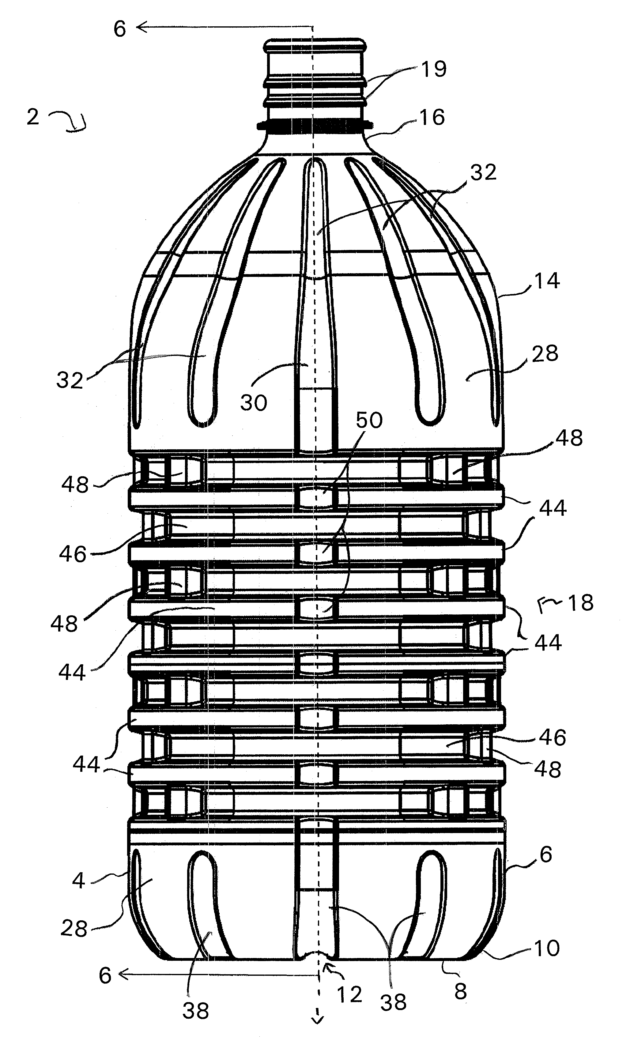
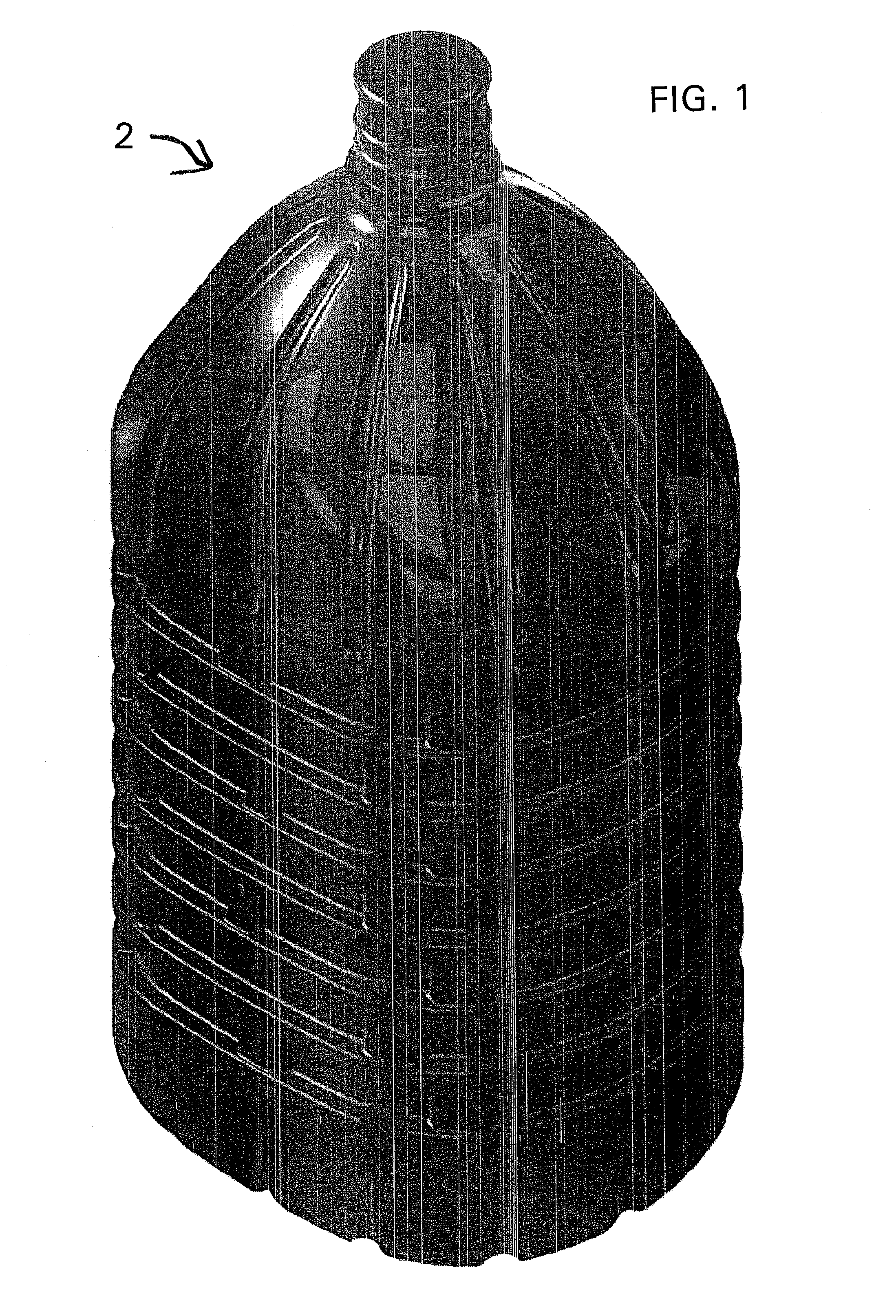
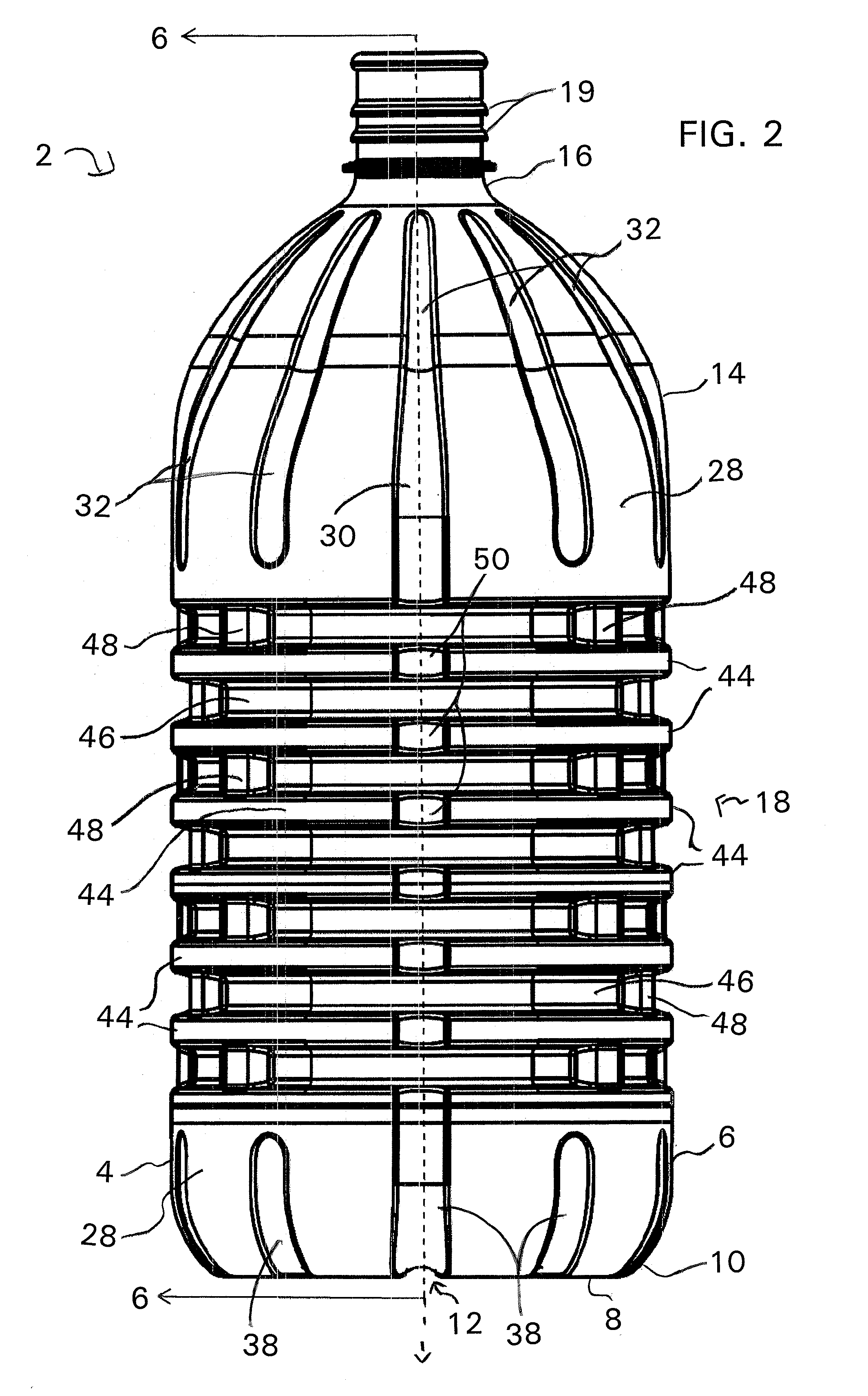
[0037]Turning now to FIGS. 1-5, a detailed description concerning the various components of a 4-gallon blow-molded water bottle or container, according to the present invention, will now be provided. As shown in those Figures, the 4-gallon stretch blow-molded water bottle or container 2 comprises a bottom portion 4 having a substantially rectangular configuration with generally curved or arcuate corner sections. The bottom portion 4 has a substantially planar vertical sidewall section 6 and a substantially planar base 8, with an arcuate transition 10 seamlessly interconnecting the sidewall section 6 with the base 8. Preferably the arcuate transition 10 has a radius of curvature of between about 3.5 and about 6.5 inches, and more preferably a radius of curvature of about 5 inches. As is conventional in the art, an inwardly push-up or chime 12 is located in the central region of the base 8. It is to be appreciated that the base 8 of the water bottle or container 2 is design to be suff...


PUM

PropertyMeasurementUnit
Massaaaaaaaaaa
Massaaaaaaaaaa
Massaaaaaaaaaa

Abstract

A multi-gallon capacity container comprising which comprises a substantially rectangular bottom portion having a chime and a plurality of base channels; a shoulder portion with a neck section for facilitating filling and discharging of liquid from the container and a plurality vertically extending shoulder channels; a body portion which seamlessly connects the bottom portion with the shoulder portion and having a plurality of spaced apart horizontal ribs and rib channels for increasing a lateral wall strength of the container. The container includes a first and second primary columns for increasing a top load strength of the container. Each primary column commences in the shoulder portion, extends substantially continuously along the shoulder portion, across the plurality of horizontal ribs, and terminates at the bottom portion. Each one of the horizontal ribs has a column feature formed therein which is aligned with one of the first and the second primary columns and forms a continuation of primary column from the shoulder portion to the bottom portion.

Description

FIELD OF THE INVENTION[0001]The present invention relates to a single use multi-gallon stretch blown plastic container, generally having a transverse rectangular cross-section, that is typically used for storage of water and has both improved top load and lateral wall strength.BACKGROUND OF THE INVENTION[0002]Water bottles and containers for water coolers generally contain between about 3-7 gallons of fluid—typically about 4 or 5 gallons of filtered or purified water. The water bottles are normally installed on the water cooler in an inverted position, with the neck of the water bottle being received by a mating receptacle of the water cooler and the neck generally supporting a majority of the weight of the water bottle. In order to dispense water from the water cooler, a standard button or handle of the water cooler is depressed or otherwise actuated in a conventional manner, which opens a conventional flow valve allowing the water, contained within an internal cavity of the water ...

Claims


Application Information

Patent Timeline
IPC IPC(8): B65D90/02B29D22/00
CPCB65D1/44B65D2501/0027B29C49/10B65D2501/0081B65D2501/0036
Inventor BECK, MARTINCONNOR, DENNISLUFKIN, KIMKOWALCZYK, JAMES
Owner DEVTECH LABS
Why Eureka
Try Eureka