System and Method for Correcting Spectral Response Using a Radiometric Correction Filter

a radiometric correction and filter technology, applied in the field of system and method for correcting spectral response using radiometric correction filter, can solve the problems of data being subjected to various optical artifacts, disrupting the efficiency of detection, and affecting the similarity of data generated

Active Publication Date: 2013-01-31
CHEMIMAGE TECH
View PDF8 Cites 10 Cited by
  • Summary
  • Abstract
  • Description
  • Claims
  • Application Information

AI Technical Summary

Benefits of technology

[0012]The custom designed filter element has a specific spectral response chosen to correct for all instrumental spectral artifacts due to other optical components including but not limited to: light source, tunable filter, optical elements, camera response, and combinations thereof. In one embodiment, each filter comprises uniquely configured thin film components. In one embodiment, the filter element described achieves real time instrument response correction by eliminating the need for separate reference measurements on known standards, such as a NIST standard reference material (“SRM”).
[0013]The present embodiments provide at least three advantages over the prior art. First, there are no spatial limitations associated with the filter described herein. Second, utilizing the filter described herein eliminates the need to separately collect correction data. This is because the data is, in a sense, already “corrected” by using the filter to collect it. Third, use of the filter is more practical than the prior art because it eliminates the need to use a standard. The correction filter described herein holds potential for application in a variety of instruments for various types of detection.

Problems solved by technology

During spectral analysis, data is subjected to various optical artifacts.
For example, putting any component in the path of light may disrupt the efficiency of detection.
As a result, the data needs to be corrected to remove these effects because when efficiency of an instrument is affected, any data generated will similarly be affected.
A disadvantage of this device is that there can be fluctuations in the transmission efficiency that depend on characteristics such as temperature, atmospheric pressure and humidity.
Due to these fluctuations, an optical instrument operating in a real-life scenario does not have a perfect or ideal performance for all wavelengths of light.

Method used


Image

  • System and Method for Correcting Spectral Response Using a Radiometric Correction Filter
  • System and Method for Correcting Spectral Response Using a Radiometric Correction Filter
  • System and Method for Correcting Spectral Response Using a Radiometric Correction Filter

Examples


Embodiment Construction

[0023]Reference will now be made in detail to the preferred embodiments of the present disclosure, examples of which are illustrated in the accompanying drawings. Wherever possible, the same reference numbers will be used throughout the drawings to refer to the same or like parts.

[0024]The present disclosure provides for a system and method which hold potential for enabling the evaluation of an imperfect optical component or system in terms of its transmission or detection performance. In the case where the component or system is stable, the present disclosure contemplates that any deviations from the perfect or ideal performance may be measured and accounted for.

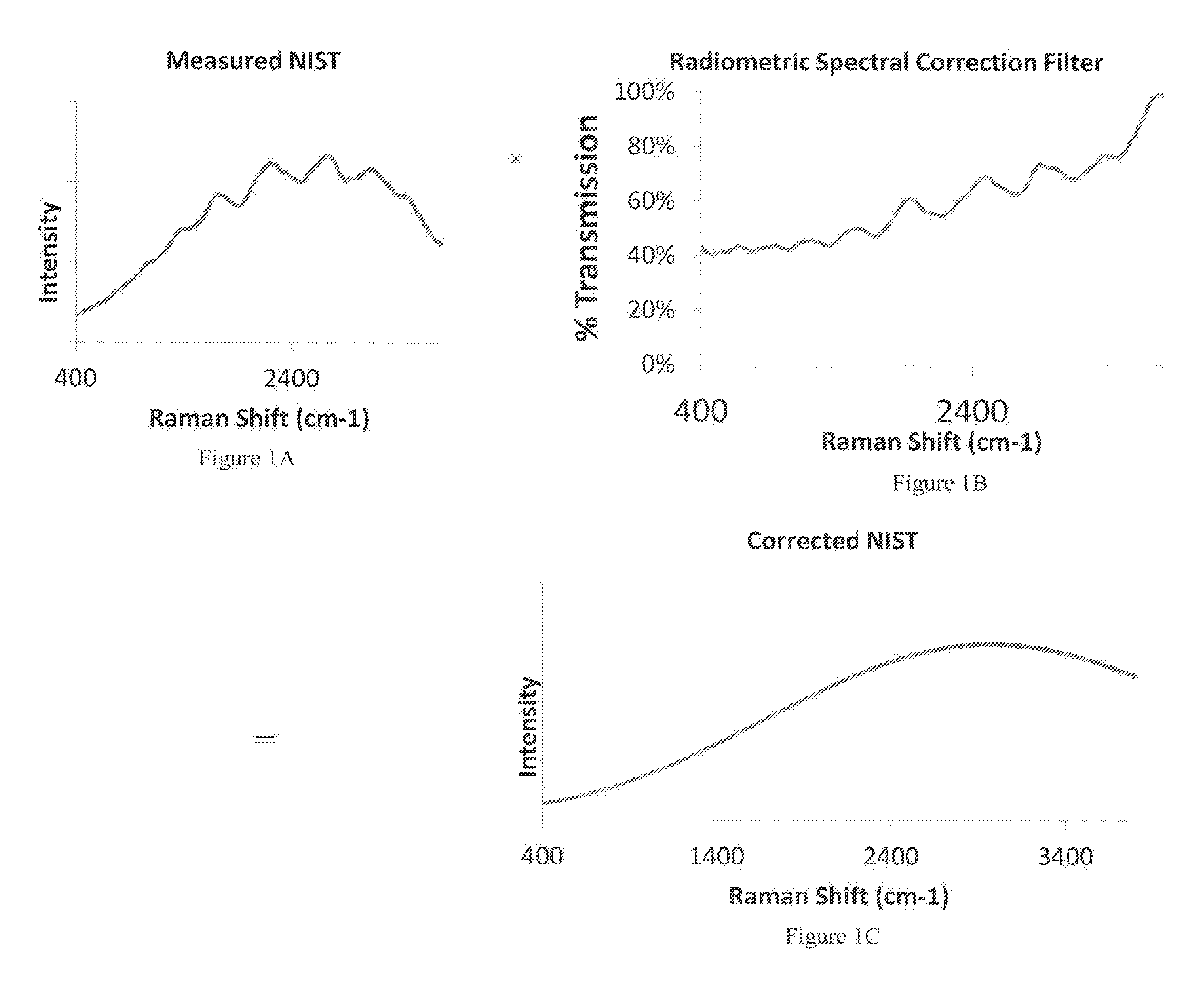
[0025]If a spectrum of this source were taken with an ideal instrument, the spectrum would be a flat horizontal line as a function of wavelength. In one embodiment, an ideal light source that produces the same number of photons at each wavelength may be used. When this ideal source is used with an imperfect instrument, howe...


PUM


Abstract

The present disclosure provides for a correction filter that may be configured to comprise a predetermined arrangement of thin film layers. This arrangement of thin film layers may be such that it effectively enables a correction filter to generate a predetermined spectral response, wherein said predetermined spectral response is substantially the same as a determined instrument response correction associated with an instrument. The invention of the present disclosure therefore provides for effectively compensating for transmission inefficiencies associated with an instrument without the need for separate reference measurements to determine and correct for instrument response.

Description

RELATED APPLICATIONS[0001]This Application is a Continuation-in-Part of the following pending U.S. Patent Applications: U.S. Publication No. US2011 / 0208462, filed on Feb. 22, 2011, entitled “System and Method for Instrument Correction Using Transmission Efficiency,” and U.S. Publication No. US2011 / 0211763, filed on Feb. 11, 2011, entitled “System and Method for Instrument Response Correction Based on Independent Measurement of the Sample.” This Application also claims priority under 35 USC §119(e) to pending U.S. Provisional Patent Application No. 61 / 431,514, filed on Jan. 11, 2011, entitled “Radiometric Spectral Response Correction Filter.” Each of the above-referenced patent applications is hereby incorporated by reference in its entirety.BACKGROUND[0002]Spectroscopic imaging combines digital imaging and molecular spectroscopy techniques, which can include Raman scattering, fluorescence, photoluminescence, ultraviolet, visible and infrared absorption spectroscopies. When applied t...

Claims


Application Information

Patent Timeline
Patent Type & Authority Applications(United States)
IPC IPC(8): G01J3/28G02B5/20G01J3/45
CPCG01J3/02G01J3/0297G01J3/44G01J2003/1213G01N21/65G01N2201/1293G01J3/28G01N21/276
Inventor PRIORE, RYANMAIER, JOHN
Owner CHEMIMAGE TECH
Why Eureka
Try Eureka