LED Lighting Device

Inactive Publication Date: 2013-01-31
CHENJUN FAN
View PDF7 Cites 23 Cited by
  • Summary
  • Abstract
  • Description
  • Claims
  • Application Information

AI Technical Summary

Benefits of technology

[0022]The light divider in the present invention may have a small shaft with a plurality of blades. While various numbers of blades are within the scope of the present invention, the preferred embodiment of the present invention has three blades that are 120 degrees apart around the shaft. In some embodiments of the present invention, the light divider sits directly on top the light distribution plate, inside the output globe, and right below the light dome, with its blades' outside perimeters in close contact with the interior surface of the output globe and the light dome. As a result, three light scrambling compartments are well defined. In other embodiments of the present invention, when the light dome is not used, the light divider sits directly on top the light distribution plate, inside the output globe, and right below the heat sink, with its blades' outside perimeters in close contact with the interior surface of the output globe and the heat sink. Also, three light scrambling compartments are well defined. The light divider's blades are lined up with the centerline of the cutouts in the heat sink so as not to interference with the LEDs mounted on the interior surface of the heat sink.
[0023]In some embodiments of the present invention, the light divider is made of a plastic material with highly efficient diffusive reflectivity. In other embodiments of the present invention, the light divider is made of a rigid substrate material coated with highly diffusively reflective paint. According to the present invention, light scrambling and light distribution can be further fine-tuned by changing the surface contour of the light divider by introducing localized micro curvatures.
[0024]Cool white light LEDs and warm white light LEDs are commercially available from Cree, Philip Lumileds, Osram, etc. These LEDs can be used in the present invention to produce a complete LED lighting device with color rendering index (CRI) specified by the LED vendors. To make sure all the light output from the standard LEDs will hit the light divider at least once before exiting from the output globe, the preferred embodiment of the present invention uses a small specular mirror right beside the LEDs to re-direct the high angle light rays towards the light divider plate, if necessary. Because the present invention provides more than adequate means to have all the light fully diffused and scrambled in the light scrambling compartments, a substantially transparent output globe can be used. Compared to the translucent output globe that is routinely used in most existing LED light bulbs, a transparent output globe can improve overall lighting efficiency.
[0025]It is widely understood that remote phosphors can improve color reproduction and luminous efficacy. Down-conversion phosphors, up-conversion phosphors, as well as RGB quantum dots may be used in the present invention. Remote phosphors can be applied in the present invention in many different ways. In some embodiments of the present invention, the light divider is made of a plastic material embedded with a plurality of phosphor particles. In other embodiments of the pr

Problems solved by technology

As a result, the thermal resistance is so high as to cause high junction temperature in LEDs.
Running an LED at elevated temperatures reduces its emission efficiency and its operation life due to degradation and premature failures.
A considerable amount of the converted light is eventually lost to absorption.
Moreover, most existing LED light bulbs have multi-phosphor self-absorption issues that cause loss of photons excited from the green and orange phosphor particles.
In some existing LED light bulbs, luminous efficacy is further reduced by visible to un

Method used


Image

  • LED Lighting Device
  • LED Lighting Device
  • LED Lighting Device

Examples


Example

[0047]Embodiments of the invention are described herein with reference to schematic illustrations of embodiments of the invention. Embodiments of the invention should not be construed as limited to the particular shapes of the regions illustrated herein but are to include deviations in shapes that result, for example, from manufacturing techniques and / or tolerances. A region illustrated or described as square or rectangular will typically have rounded or curved features due to normal manufacturing tolerances. Thus, the regions illustrated in the figures are schematic in nature and their shapes are not intended to illustrate the precise shape of a region of a device and are not intended to limit the scope of the invention.

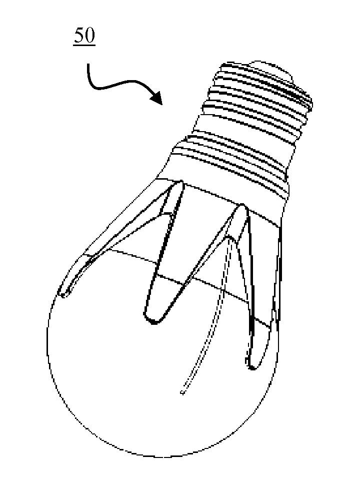
[0048]The present invention will now be described with reference to FIG. 1. While various shapes of the lighting devices are within the scope of the present invention, the preferred embodiment of the present invention has a shape and form factor closely resembling t...


PUM


Abstract

A solid-state light emitting diode (LED) lighting device is disclosed for use in general lighting. In the preferred embodiment, the LED lighting device comprises a heat sink, a light dome, a light divider, a light distribution plate, and an output globe. A plurality of diffusively reflective compartments are formed inside the output globe for effective light scrambling. The light distribution plate, together with a shaped heat sink and a substantially transparent matching output globe, further enhances omni-directional lighting distribution and luminous efficacy. In some preferred embodiments, color mixing or remote wavelength conversion luminescent phosphor particles are utilized for improved color reproduction. The LED lighting device has high luminous efficacy, indirect glare-free surface illumination, omni-directional distribution, and good color reproduction.

Description

CROSS-REFERENCE TO RELATED APPLICATIONS[0001]This application claims priority of U.S. Provisional Patent Application No. 61 / 513,241 filed on Jul. 29, 2011, entitled “LED Lighting Device” which is incorporated herein by reference for all purposes.FIELD OF THE INVENTION[0002]This invention generally relates to solid-state lighting devices, as well as related components, systems and methods, and more particularly to methods to make a warm white LED light bulb with high luminous efficacy, omni-directional distribution, and high color rendering.BACKGROUND OF THE INVENTION[0003]Because solid-state semiconductor light emitters are environmentally friendly and have a big potential in energy saving and long operation life in comparison with traditional lighting devices, solid-state light emitting apparatus are being widely designed and marketed as replacements for conventional incandescent lighting apparatus. There have been considerable efforts to replace incandescent light bulb using solid...

Claims


Application Information

Patent Timeline
IPC IPC(8): F21V29/00F21V9/16F21V11/00
CPCF21V29/00F21V9/16F21V11/00F21V29/74F21K9/13F21Y2101/02F21V29/004F21Y2115/10
Inventor FAN, CHENJUN
Owner CHENJUN FAN
Why Eureka
Try Eureka