Moving image prediction encoder, moving image prediction decoder, moving image prediction encoding method, and moving image prediction decoding method

a technology of moving image and encoder, which is applied in the field of video prediction encoder, video prediction decoder, video prediction encoding method, and video prediction decoding method, can solve the problems of image quality degradation and insufficient removal of block distortion, so as to improve the efficiency of predicting pictures and improve the quality of reproduced pictures

Inactive Publication Date: 2013-01-31
NTT DOCOMO INC
View PDF1 Cites 27 Cited by
  • Summary
  • Abstract
  • Description
  • Claims
  • Application Information

AI Technical Summary

Benefits of technology

[0014]Therefore, there are demands for a new method which can improve the quality of reproduced pictures and improves the efficiency of predicting pictures encoded with the reproduced pictures used as reference pictures.
[0018]According to the video prediction encoder, video prediction encoding method, and video prediction encoding program as described above, a filtering strength and target region to be filtered are determined based on the parameters used to perform the luminance compensated prediction between blocks and the reproduced picture is then filtered. Thereafter, the reproduced picture as filtered is stored as a reference picture to be used to encode a subsequent picture. By using, for filtering, the parameters to perform the luminance compensation prediction, even when there is a difference in luminance compensation prediction between blocks, it becomes possible to perform filtering according to the difference. As a result, it becomes possible to improve the quality of reproduced pictures and improve the efficiency of predicting pictures encoded with the reproduced pictures used as reference pictures.
[0020]In this case, since the filtering strength and the target region to be filtered are determined based on a difference in the parameters between mutually adjacent blocks, it becomes possible to suppress block distortions likely to occur in a block boundary region. As a result, it becomes possible to improve the quality of reproduced pictures and the prediction efficiency for pictures.
[0029]According to the video prediction decoder, the video prediction decoding method, and the video prediction decoding program as described above, a filtering strength and a target region to be filtered are determined based on the parameters for the luminance compensation prediction between blocks and then filtering is performed on reproduced pictures. Thereafter, the filtered reproduced pictures are stored as reference pictures to be used to decode subsequent pictures. Since the filtering is performed, given the parameters for the luminance compensation prediction, even when there is a difference in luminance compensation prediction between blocks, the filtering can be performed according to the difference. As a result, it becomes possible to improve the quality of reproduced pictures and improve the efficiency of predicting pictures decoded with the reproduced pictures used as reference pictures.
[0031]In this case, since the filtering strength and the target region to be filtered are determined based on a difference of the parameters between the adjacent blocks, it becomes possible to suppress block distortions likely to occur in a block boundary region. As a result, it becomes possible to improve the quality of reproduced pictures and the efficiency of predicting pictures.
[0037]According to the video prediction encoder, the video prediction decoder, the video prediction encoding method, the video prediction decoding method, the video prediction encoding program, and video prediction decoding program as described above, since the filtering is performed, given the parameters for the luminance compensation prediction, it becomes possible to improve the quality of reproduced pictures and improve the efficiency of predicting pictures encoded with the reproduced pictures used as reference pictures.

Problems solved by technology

For this reason, there are cases where the image quality degrades due to excessive filtering which blurs the image or due to insufficient filtering which causes insufficient removal of block distortions or quantization distortions.

Method used


Image

  • Moving image prediction encoder, moving image prediction decoder, moving image prediction encoding method, and moving image prediction decoding method
  • Moving image prediction encoder, moving image prediction decoder, moving image prediction encoding method, and moving image prediction decoding method
  • Moving image prediction encoder, moving image prediction decoder, moving image prediction encoding method, and moving image prediction decoding method

Examples


Embodiment Construction

[0053]Embodiments of the present invention will be described below in detail with reference to the accompanying drawings. In the description of the drawings, identical or equivalent elements will be represented by the same reference signs, and redundant descriptions thereof will be omitted.

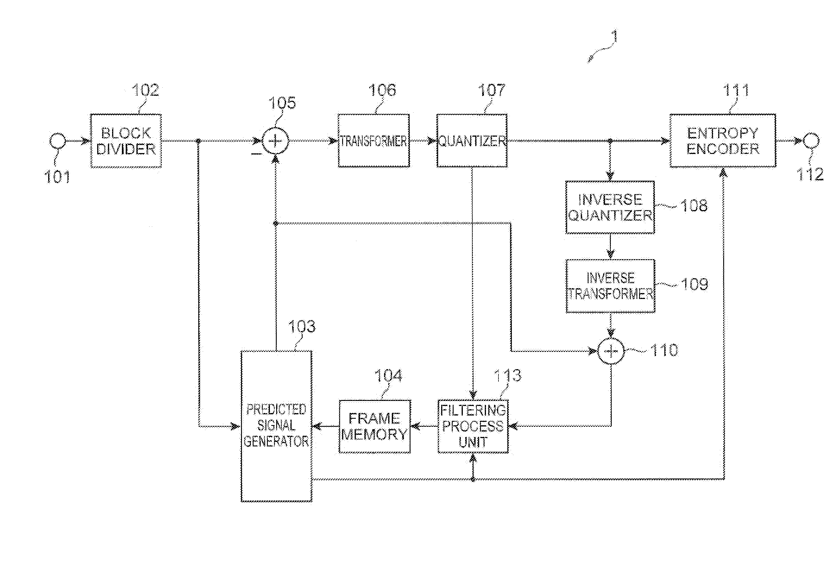
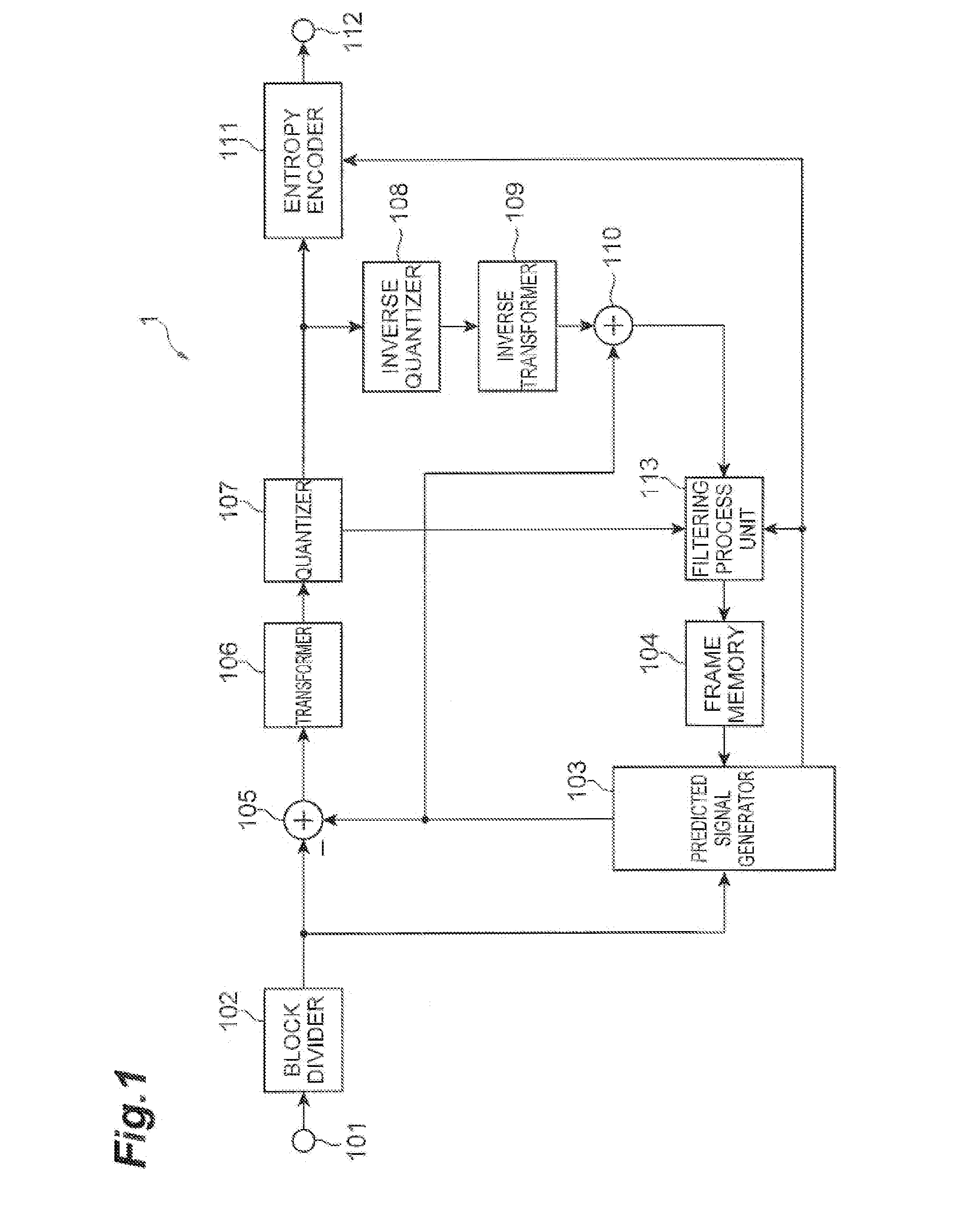
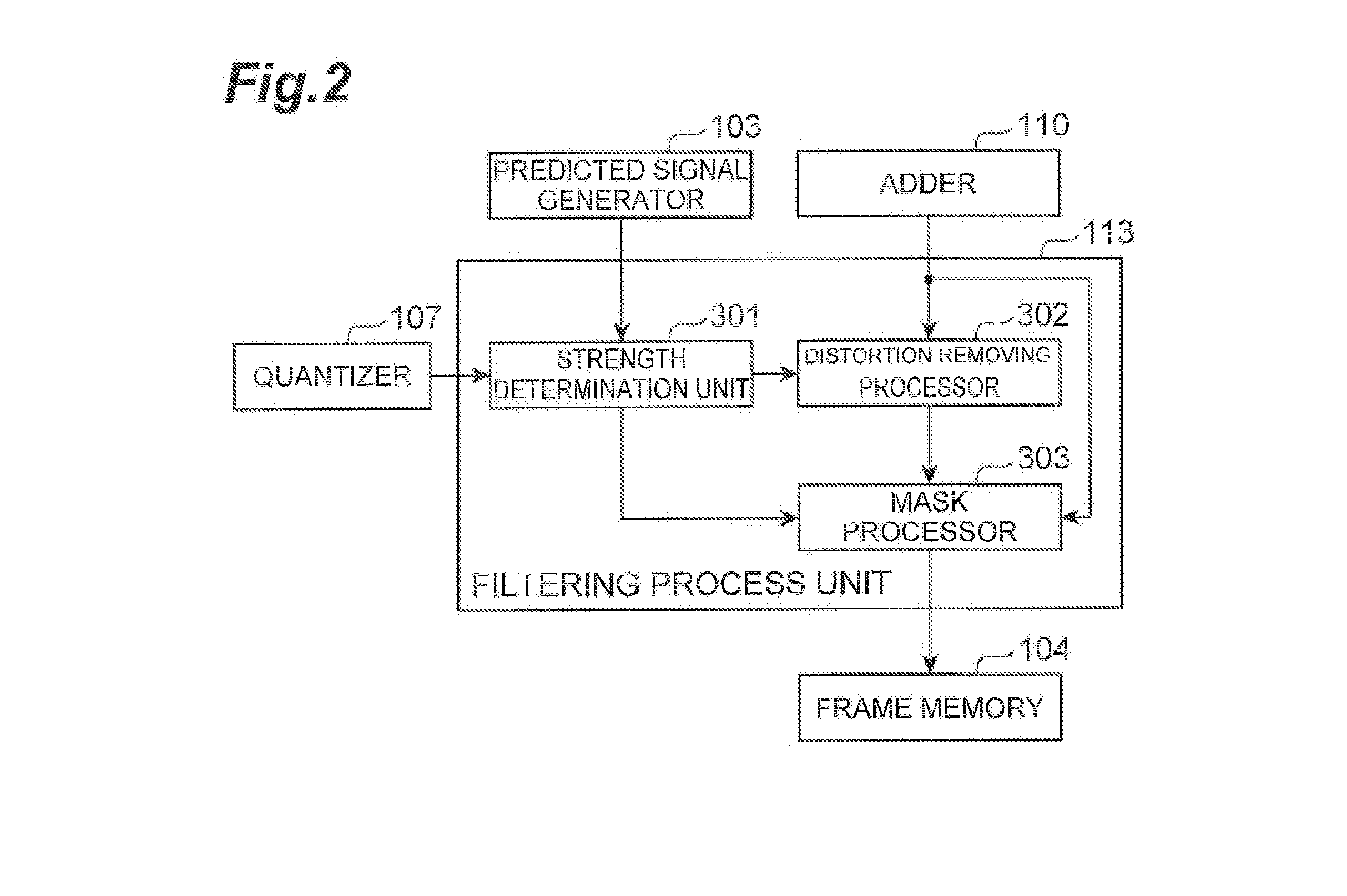
[0054]First, the functions and configuration of a video prediction encoder according to an embodiment of the present Invention will be described using FIGS. 1 to 8. FIG. 1 is a block diagram showing the functional configuration of a video prediction encoder 1 (which will also be referred to hereinafter simply as an encoder 1) according to the embodiment. FIG. 2 Is a block diagram showing the functional configuration of a filtering processor 113. FIG. 3 is a drawing for explaining a process by a strength determination unit 301. FIG. 4 is a flowchart showing the process by the strength determination unit 301. FIG. 5 is a block diagram showing the functional configuration of a distortion removing pro...


PUM


Abstract

An object is to improve the quality of a reproduced picture and improve the efficiency of predicting a picture using the reproduced picture as a reference picture. For this object, a video prediction encoder 1 comprises an input terminal 101 which receives a plurality of pictures in a video sequence; an encoder which encodes an input picture by intra-frame prediction or inter-frame prediction to generate compressed data and encodes parameters for luminance compensation prediction between blocks in the picture: a restoration device which decodes the compressed data to restore a reproduced picture: a filtering processor 113 which determines a filtering strength and a target region to be filtered, using the parameters for luminance compensation prediction between the blocks and performs filtering on the reproduced picture, according to the filtering strength and the target region to be filtered; and a frame memory 104 which stores the filtered reproduced picture, as a reference picture.

Description

RELATED APPLICATIONS[0001]This application is a continuation of PCT / JP2011 / 058439 filed on Apr. 1,2011, which claims priority to Japanese Application No. 2010-089629 filed on Apr. 8, 2010. The entire contents of these applications are incorporated herein by reference.TECHNICAL FIELD[0002]The present invention relates to a video prediction encoder, video prediction decoder, video prediction encoding method, and video prediction decoding method.BACKGROUND ART[0003]Compression techniques are used for efficient transmission and storage of video data, The techniques according to MPEG1-4 and H.261-IL264 are widely used for compressing moving images. In these compressing techniques, a target picture to be encoded is divided into a plurality of blocks which are then subjected to encoding and decoding. The prediction encoding methods as described below are used for enhancement of encoding efficiency.[0004]In infra-frame prediction encoding, a prediction signal of a target block to be encoded...

Claims


Application Information

Patent Timeline
Patent Type & Authority Applications(United States)
IPC IPC(8): H04N7/32H04N19/50H03M7/36H04N19/117H04N19/136H04N19/139H04N19/157H04N19/176H04N19/196H04N19/423H04N19/503H04N19/577H04N19/593H04N19/60H04N19/61H04N19/80H04N19/82H04N19/91
CPCH04N19/82H04N19/61
Inventor FUJIBAYASHI, AKIRABOON, CHOONG SENGKANUMURI, SANDEEPTAN, THIOW KENG
Owner NTT DOCOMO INC
Why Eureka
Try Eureka