Blade cooling and sealing system

a gas turbine engine and sealing technology, applied in the direction of liquid fuel engines, vessel construction, marine propulsion, etc., can solve the problems of affecting engine performance, unable to generate useful work, and air that is bled from the compressor prior to combustion (i.e. air that has bypassed), and achieves the effect of less air

Inactive Publication Date: 2013-01-31
ROLLS ROYCE PLC
View PDF10 Cites 12 Cited by
  • Summary
  • Abstract
  • Description
  • Claims
  • Application Information

AI Technical Summary

Benefits of technology

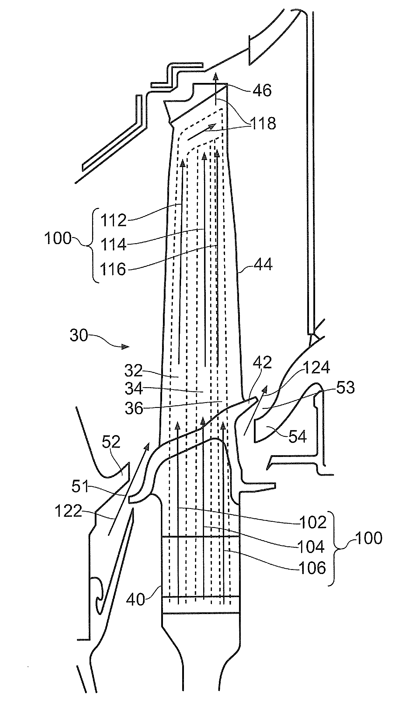
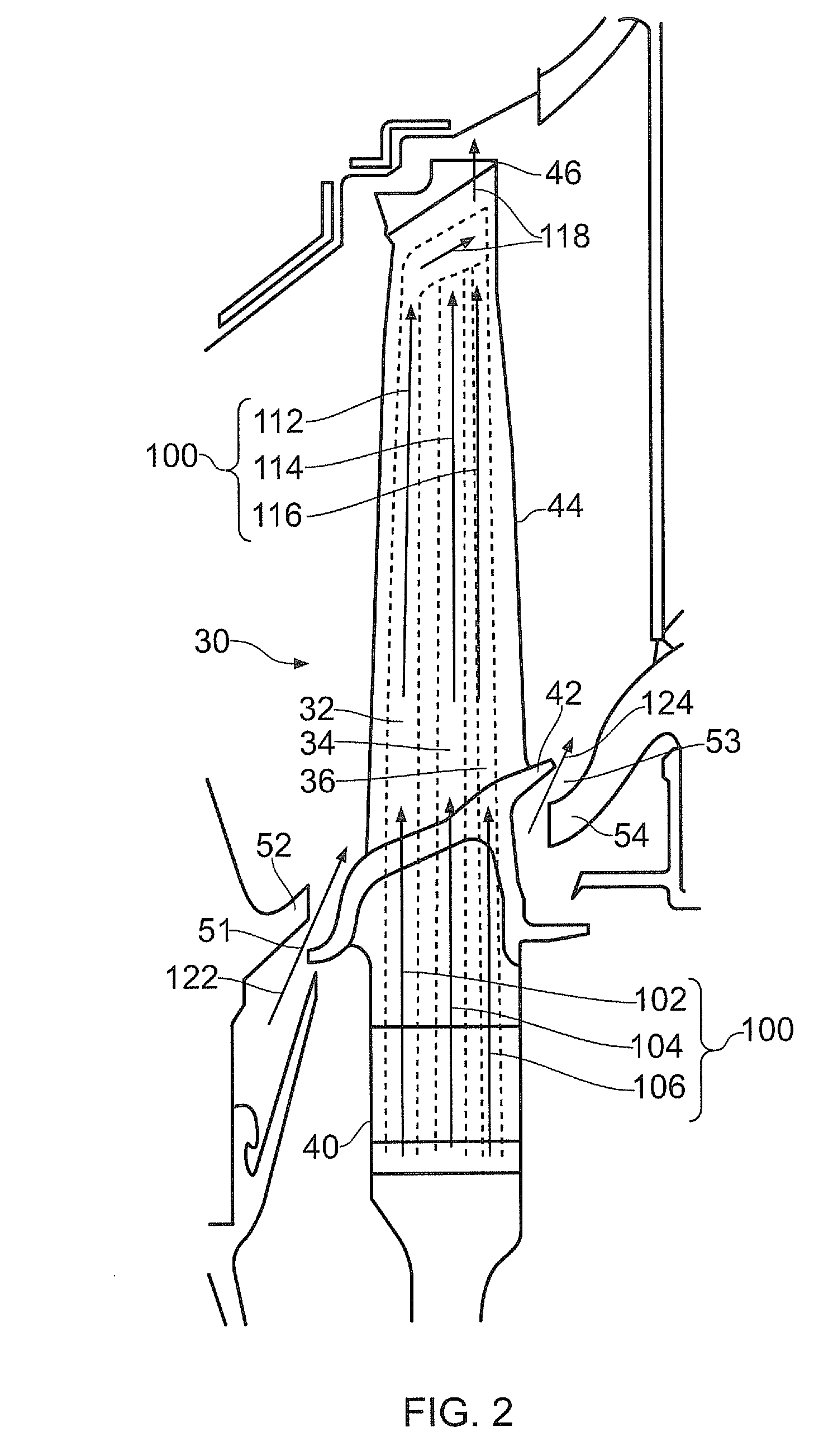
[0011]The aerofoil may include aerodynamic surfaces that, in operation, are gas-washed by the working fluid, such as a suction surface, a pressure surface, and a platform from which the suction surface and pressure surface extend. The blade or vane may comprise sealing features which may combine or interact with (for example interlock with, abut, or nearly abut) neighbouring surfaces (for example of neighbouring blades or vanes) of a gas turbine engine to form a seal when assembled. The blade or vane may optionally include a shroud at its tip. The shroud may include sealing features to prevent or reduce over-tip leakage flow, for example in blade embodiments. The shroud may extend around the entire outer circumference of the blades. Alternatively, the blade or vane may have a partial shroud, or winglet, at its tip (for example extending around a portion of the segment between the blades). Alternatively still, the blade or vane may have no shroud at its tip.
[0039]The flow that is used for cooling and sealing may be bled from a compressor of the gas turbine engine before entry into a combustor. Thus, using at least a portion of the flow for both cooling and sealing means that less air needs to be bled from the compressor and / or that more heat can be removed from a given blade or vane for a given amount of air bled from the compressor.

Problems solved by technology

As mentioned above, air that is bled from the compressor prior to combustion (i.e. air that has bypassed the combustor) cannot be used to generate useful work.
Extracting air from the compressor, for example for cooling the hot turbine components or for providing a sealing flow, therefore has an adverse effect on engine performance, such as operating efficiency.

Method used


Image

  • Blade cooling and sealing system
  • Blade cooling and sealing system
  • Blade cooling and sealing system

Examples


Embodiment Construction

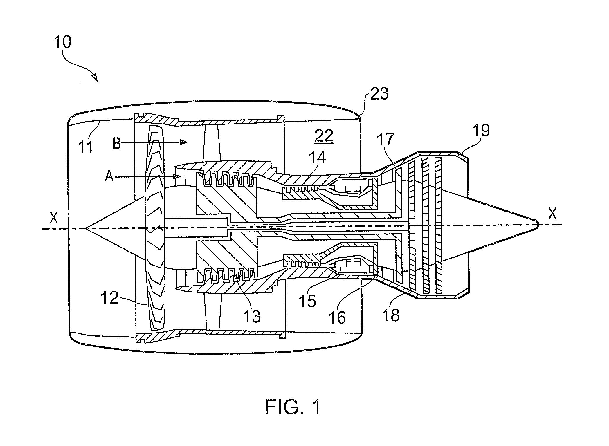
[0047]With reference to FIG. 1, a ducted fan gas turbine engine generally indicated at 10 has a principal and rotational axis X-X. The engine 10 comprises, in axial flow series, an air intake 11, a propulsive fan 12, an intermediate pressure compressor 13, a high-pressure compressor 14, combustion equipment 15, a high-pressure turbine 16, an intermediate pressure turbine 17, a low-pressure turbine 18 and a core engine exhaust nozzle 19. A nacelle 21 generally surrounds the engine 10 and defines the intake 12, a bypass duct 22 and a bypass exhaust nozzle 23.

[0048]The gas turbine engine 10 works in a conventional manner so that air entering the intake 11 is accelerated by the fan 12 to produce two air flows: a first air flow A into the intermediate pressure compressor 13 and a second air flow B which passes through the bypass duct 22 to provide propulsive thrust. The intermediate pressure compressor 13 compresses the air flow A directed into it before delivering that air to the high p...


PUM


Abstract

A cooled component for a gas turbine engine, for example a turbine rotor blade, is provided. The component has an internal cooling flow passage. Cooling air is passed through the internal cooling flow passage to remove heat from the component and thereby reduce its temperature. The cooling air is bled from the internal cooling passage after it has passed through a portion of the passage into an internal bleed flow passage. This bled air is then used in a seal. Thus, some of the cooling air that enters the internal cooling flow passage is used both to cool the component and to form a seal, for example with another component.

Description

CROSS-REFERENCE TO RELATED APPLICATIONS[0001]This application is based upon and claims the benefit of priority from British Patent Application Number 1112880.8 filed 27 Jul. 2011, the entire contents of which are incorporated by reference.BACKGROUND OF THE INVENTION[0002]1. Field of the Invention[0003]The present invention concerns cooling and sealing arrangements in a gas turbine engine. In particular, the present invention concerns a method and apparatus for using flow to cool components in a gas turbine engine and seal between components of a gas turbine engine.[0004]2. Description of the Related Art[0005]The performance of a gas turbine engine, for example measured in terms of efficiency or specific output, may be improved by increasing the turbine gas temperature. It is therefore generally desirable to operate the turbine at the highest possible temperature. For a given gas turbine configuration (for example in terms of engine cycle compression ratio or bypass ratio), increasin...

Claims


Application Information

Patent Timeline
Patent Type & Authority Applications(United States)
IPC IPC(8): F01D5/08
CPCF01D5/187F01D11/04F01D5/225F05D2260/60F05D2250/75
Inventor BURT, ALEXANDER J.SADLER, KEITH C.GORTON, KEVIN
Owner ROLLS ROYCE PLC
Why Eureka
Try Eureka