Drive device

a technology of drive unit and drive shaft, which is applied in the direction of sea energy generation, engine fuction, tidal stream/damless hydropower, etc., can solve the problem of not focusing on the constructional features of the drive unit of the winch, and achieve the effect of running the winch smoothly and efficiently and light weigh

Active Publication Date: 2013-01-31
FOBOKS AS
View PDF64 Cites 8 Cited by
  • Summary
  • Abstract
  • Description
  • Claims
  • Application Information

AI Technical Summary

Benefits of technology

[0012]The present invention aims to meet the above need hitherto not taught by prior art, by providing a specially constructed drive device for a winch, which by virtue

Problems solved by technology

Although, this prior art discloses a drive unit coupled to the drive shaft, it

Method used


Image

  • Drive device
  • Drive device
  • Drive device

Examples


Embodiment Construction

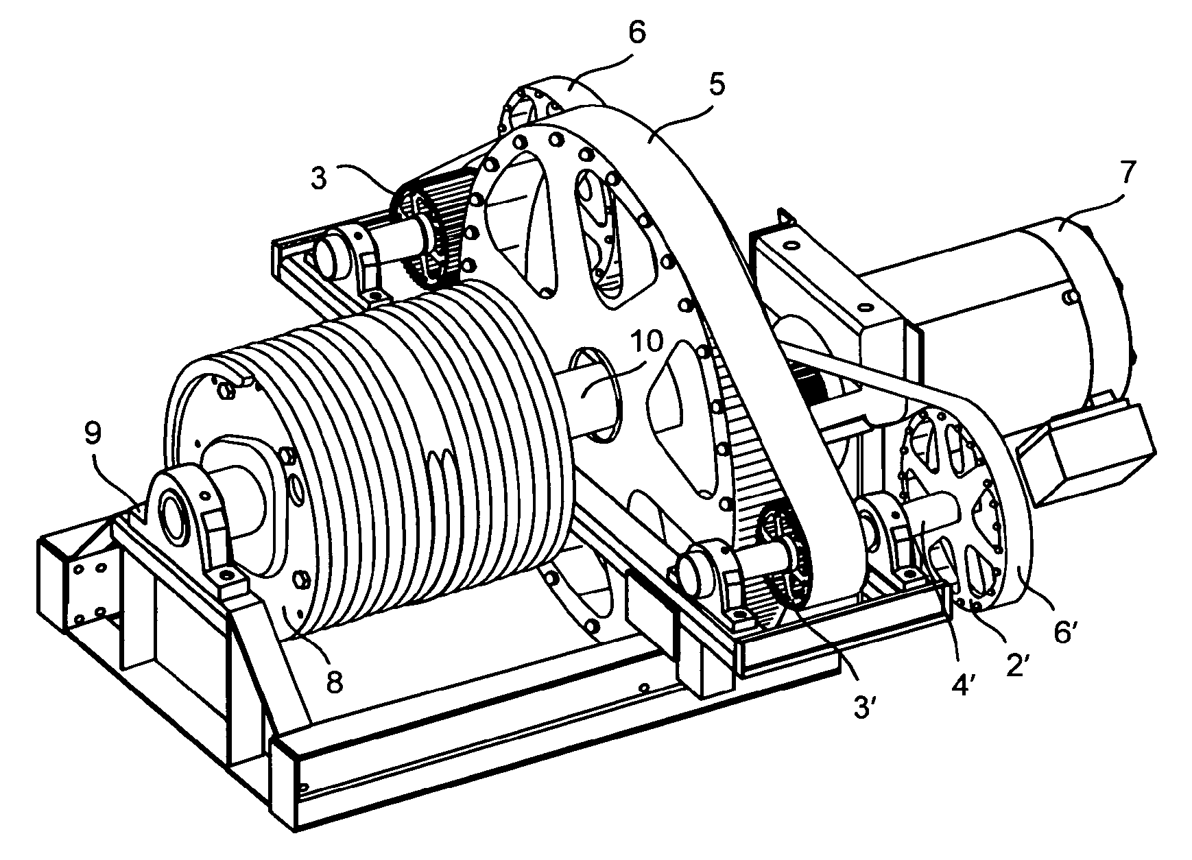
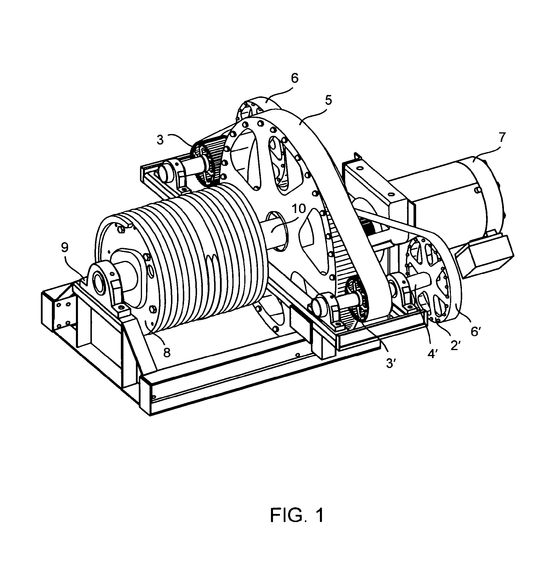
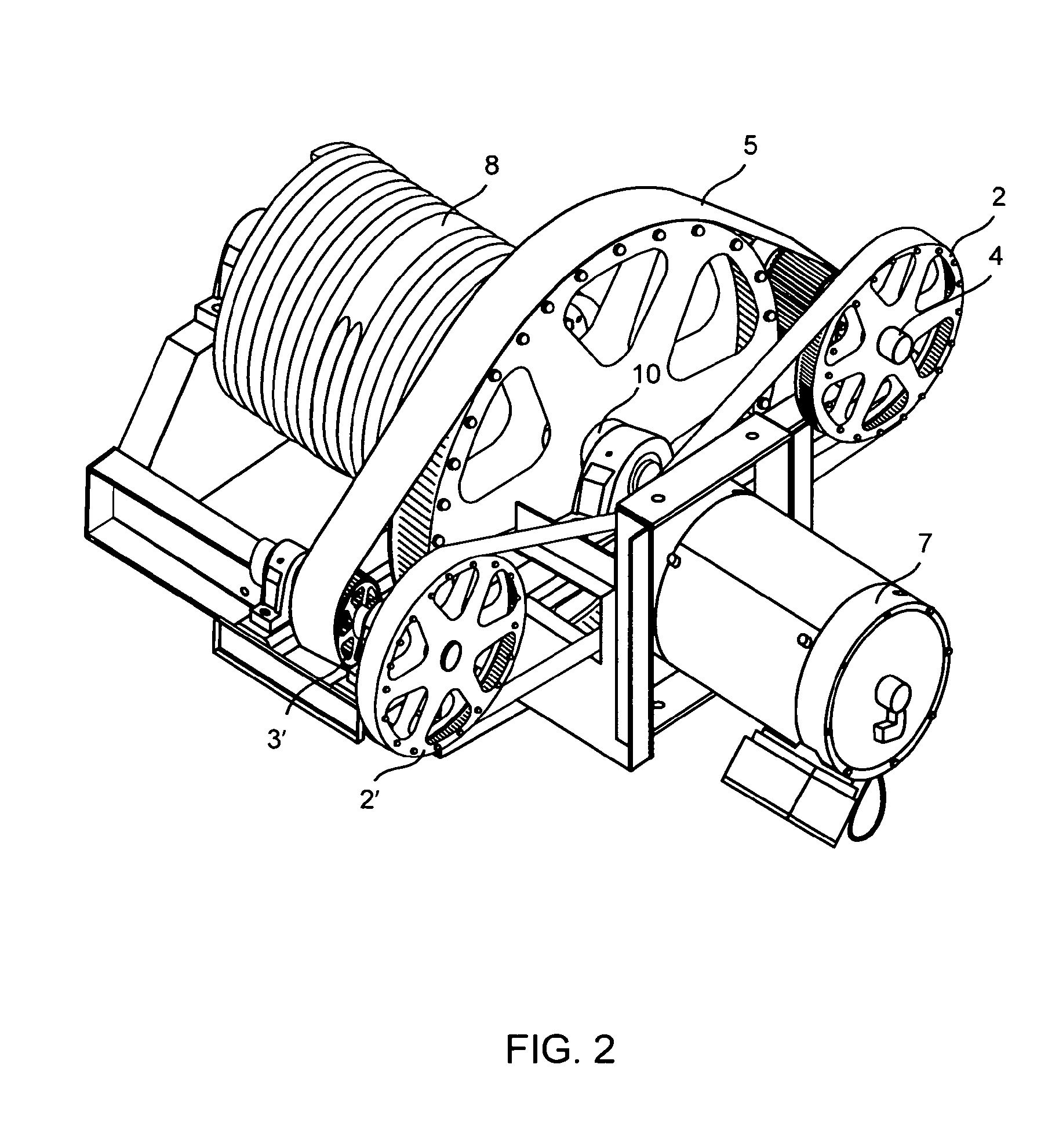
[0053]The accompanying FIG. 1 illustrates a preferred embodiment of the drive device according to the present invention for driving a winch. It shows the drive device when viewed from the winch drum end. The accompanying FIG. 2 shows the same device from the motor end. In this context, it is hereby clarified that the winch drive illustrated in the accompanying FIGS. 1 to 5 is only by way of example and illustration and such drive is equally effective in its application for driving floating vessel propellers (FIGS. 6 to 9) and for running electric generators in tidal power plants (FIG. 10) and essentially runs on the same principle.

[0054]The drive device comprises a large belt pulley 1 or chain pulley mounted on a rotatable main shaft 10. The large belt pulley 1 is connected to a winch drum 8 along the shaft 10. The winch drum is preferably supported on a bearing housing 9. The large belt pulley 1 is also rotatably connected to a generator / motor 7, that being the prime mover, which i...


PUM


Abstract

A drive device for a winch (8) comprising a large belt pulley (1) or chain pulley, a winch drum which is connected to the large belt pulley (1). The large belt pulley (1) is rotatably connected to at least one prime mover such as a motor (7). The device has at least two rotatable secondary shafts (4, 4′), each being parallel to the rotational axis of said belt pulley (1). The secondary shafts (4, 4′) are in rotational connection with the large belt pulley (1) via at least one belt/chain. The motor is in rotational connection with one of the secondary shafts. Drive devices according to the same principles for a floating vessel propeller, a hydro turbine and a wave power plant are also described.

Description

FIELD OF THE INVENTION[0001]The present invention in general relates to a drive device, which, e.g., can be used for a winch, as a ship propulsion drive, thrusters, as or tidal plants. The drive is adapted to have a simplified and compact construction, ensures that the torque over the drive shaft is balanced, is light weight and also has substantially reduced number of components and requires minimum maintenance. In particular, the present invention provides a drive device according to the preamble of the following claims 1, 2, 3 and 4,TECHNICAL BACKGROUND OF THE INVENTION[0002]Winches are known to persons skilled in the art to have a wide range of applications wherever there is a requirement for lifting and releasing of load, involving a high torque. For example in oil platforms, floating platforms, sailing boats, elevators, anchoring of boats, drilling operations, cargo loading and unloading, E.O.T cranes, building constructions and so on.[0003]It is also known that diesel electri...

Claims


Application Information

Patent Timeline
IPC IPC(8): F16H7/02F16H7/06
CPCB66D1/20F03B17/061F05B2260/4021F16H7/02Y02E10/28Y02E10/38F05B2260/403Y02E10/30B63H23/04F03B13/20F03B13/26Y02E10/20
Inventor TJENSVOLL, GAUTE
Owner FOBOKS AS
Why Eureka
Try Eureka