
Method and system for measuring the impedance of the power distribution network in programmable logic device applications

a technology of programmable logic devices and power distribution networks, applied in resistance/reactance/impedence, voltage-current phase angles, instruments, etc., can solve problems such as major disruption of electronic systems, and achieve the effects of reducing power consumption, increasing the impedance of power distribution, and saving costs

Active Publication Date: 2013-01-31
NOISECOUPLING LLC
View PDF4 Cites 10 Cited by
  • Summary
  • Abstract
  • Description
  • Claims
  • Application Information

AI Technical Summary

Benefits of technology

This patent describes a method to measure power distribution in electronic systems using programmable logic devices (PLDs). By using resources that are not specifically built-in for power distribution measurements, this invention can be used with most existing PLDs on the market, such as FPGAs and CPLDs. The method allows for temporary use of PLD resources for troubleshooting or characterization purposes, saving cost and reducing power consumption. It also enables remote troubleshooting of electronic systems that use PLDs, providing a more convenient and minimally invasive solution.

Problems solved by technology

As a direct consequence, a burned capacitor becomes an open circuit and does not perform the intended power distribution decoupling function.
One way to detect an increase of power distribution impedance is to measure it; however, most existing techniques require major disruption of the electronic system to get access to measurement nodes and connect measurement instruments.

Method used


Image

  • Method and system for measuring the impedance of the power distribution network in programmable logic device applications
  • Method and system for measuring the impedance of the power distribution network in programmable logic device applications
  • Method and system for measuring the impedance of the power distribution network in programmable logic device applications

Examples


Embodiment Construction

[0029]The description presented herein will focus on a system and method implemented in a programmable logic device (PLD) and more specifically in a field programmable gate array (FPGA); however, it is significant to note that the enclosed embodiments are not to be considered as limiting. Those skilled in the art will appreciate that the concepts and embodiments of the present invention may be applied to various types of programmable devices and integrated circuits.

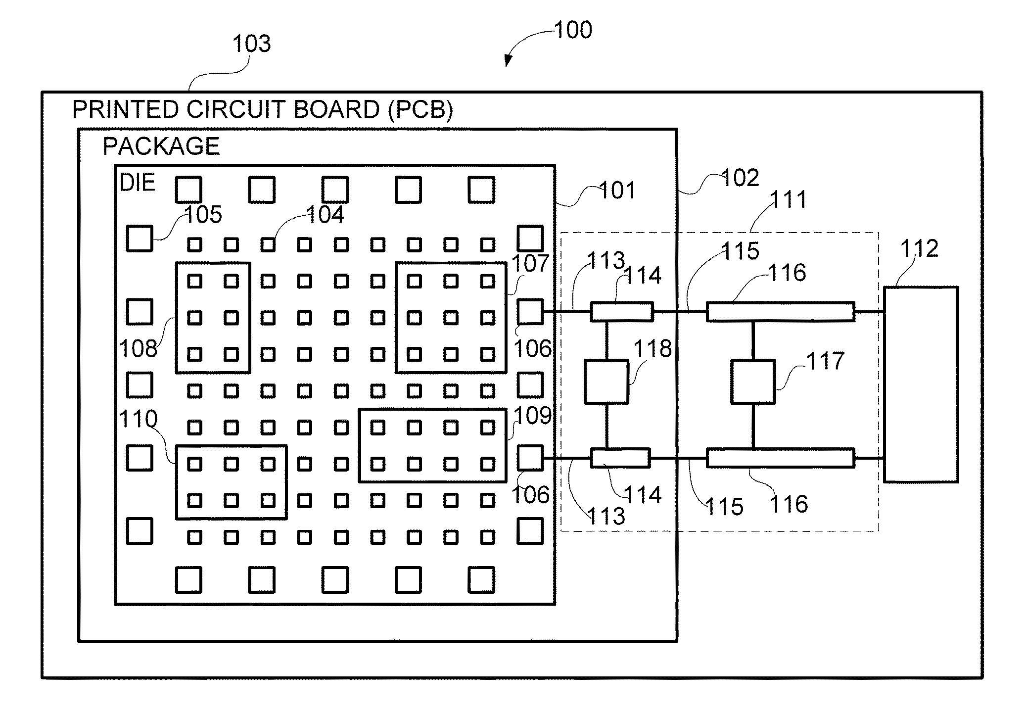
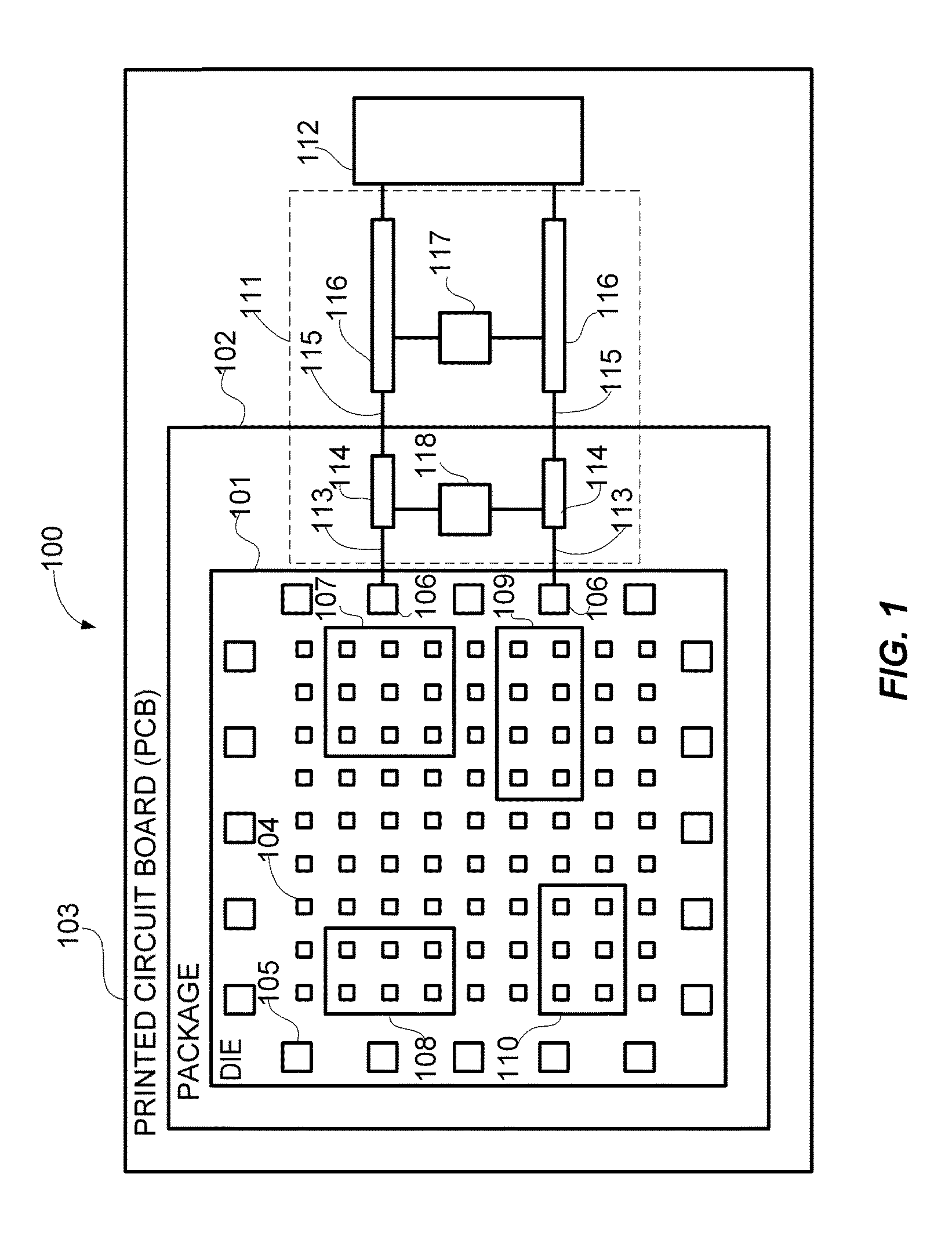
[0030]Turning now to the drawing representing the current invention, FIG. 1 illustrates a structural diagram, generally designated 100, of a programmable logic device die 101 connected to a power distribution network 111 and configured to measure the electrical impedance of the power distribution network according to an embodiment of the present invention. Programmable logic device die 101 has been mounted in package 102. The package 102 has been mounted on printed circuit board 103. Programmable logic device die 101 cont...


PUM


Abstract

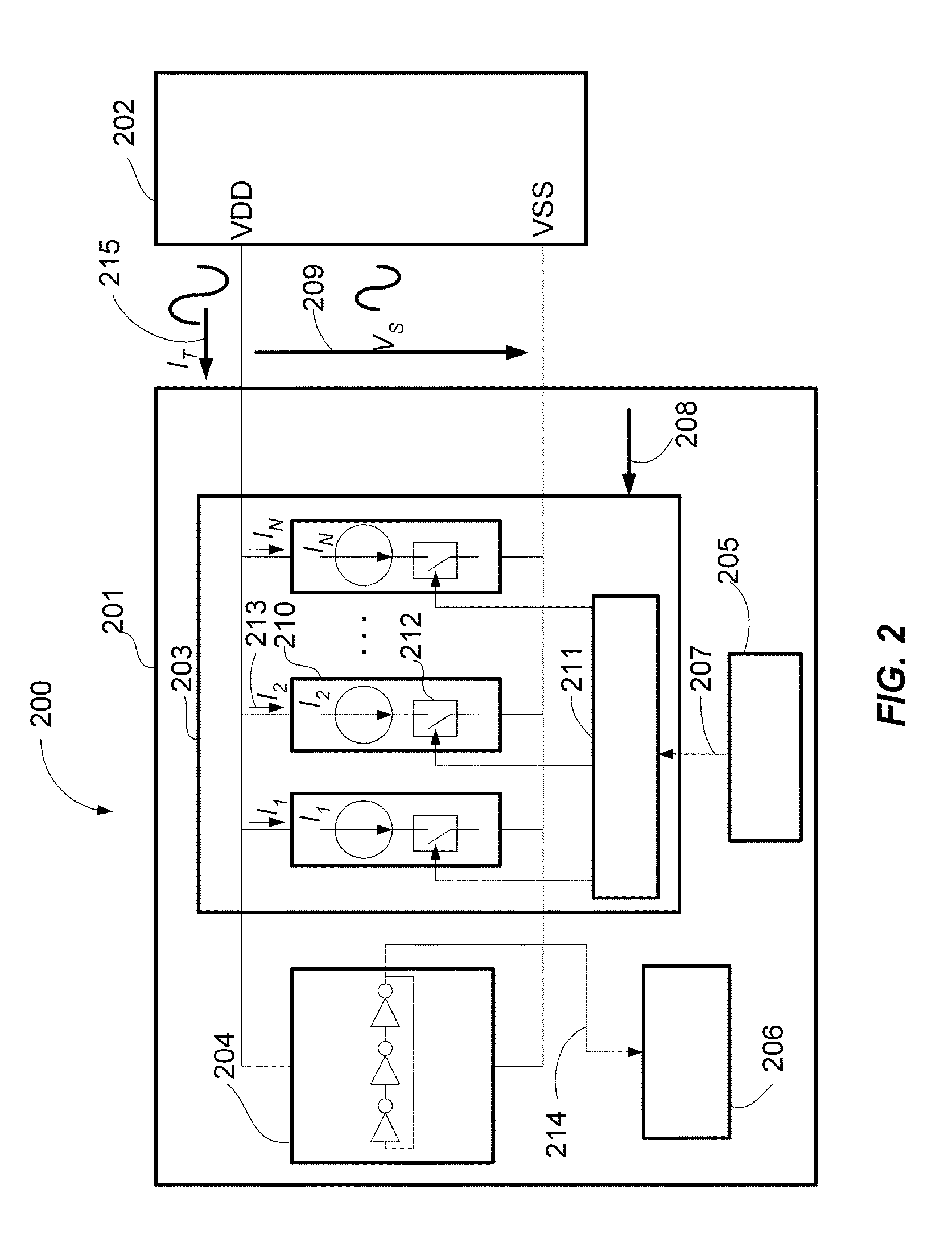
On-die measurement of power distribution impedance frequency profile of a programmable logic device (PLD), such as field programmable gate array (FPGA) or complex programmable logic device (CPLD), is performed by configuring and using only logic blocks resources commonly available in any existing programmable logic device, without the need of built-in dedicated circuits. All measurements are done inside the programmable logic device without the need of external instruments. The measurement method can be used during characterization to select decoupling capacitors or for troubleshooting existing systems, after which the programmable logic device may be reconfigured to perform any other user-defined function.

Description

CROSS-REFERENCE TO RELATED APPLICATIONS[0001]This application claims the benefit of U.S. Provisional Patent application Ser. No. 61 / 511,547 entitled “SYSTEM AND METHOD FOR CONFIGURING A PROGRAMMABLE LOGIC DEVICE INTEGRATED CIRCUIT TO MEASURE ON-DIE THE ELECTRICAL IMPEDANCE OF ITS POWER DISTRIBUTION NETWORK CIRCUIT” which was filed Jul. 25, 2011. The entirety of the aforementioned application is herein incorporated by reference.FIELD OF THE INVENTION[0002]This invention relates to programmable logic devices integrated circuits, and more particularly to measuring the power distribution impedance of a programmable logic device connected to a power distribution network circuit.BACKGROUND OF THE INVENTION[0003]Programmable logic devices (PLD) such as field programmable gate arrays (FPGA) and complex programmable logic devices (CPLD), are integrated circuits that can be programmed by users to perform customized logic functions. In a typical design process a user defines customized logic f...

Claims


Application Information

Patent Timeline
Patent Type & Authority Applications(United States)
IPC IPC(8): G06F19/00
CPCG01R31/31721G01R31/318519
Inventor IORGA, COSMIN
Owner NOISECOUPLING LLC
Learn More