Lamp assembly and circuits for protection against miswiring in a lamp controller

a technology for led drivers and lamps, which is applied in the direction of emergency protective circuit arrangements, energy-saving lighting, sustainable buildings, etc., can solve the problems of current condition, miswiring of leads, and burnout of electronic ballast circuitry, and achieve the effect of simple and effectiv

Active Publication Date: 2013-02-07
GE LIGHTING SOLUTIONS LLC
View PDF4 Cites 13 Cited by
  • Summary
  • Abstract
  • Description
  • Claims
  • Application Information

AI Technical Summary

Benefits of technology

[0007]Non-limiting aspects of the present subject matter relate to unique miswiring protection circuits for an electronic ballast or LED driver circuit in a gas discharge lamp or LED light, respectively. The protection circuits are relatively simple and effective, and do not have the disadvantages of the circuits based on conventional PTC thermistors or depletion mode MOSFETS discussed above.

Problems solved by technology

Despite appropriate color coding of each set of leads, miswiring of the leads continues to be a problem in the field wherein the low voltage signal leads intended for connection to the controller are mistakenly connected to a line voltage power source.
This miswiring may lead to an over current condition and burn out of the electronic ballast circuitry.
A drawback, however, with conventional PTC configurations is that where the circuitry is encased in a potting compound, it is necessary to isolate the PTC from the potting compound to protect the potting compound from the elevated temperatures generated by the PTC in the event of miswiring.
This has resulted in added cost due to the necessity of rearranging the circuitry to isolate the PTC.
Depletion mode MOSFET devices are, however, relatively expensive and add to the overall cost of gas discharge lamp circuitry.

Method used


Image

  • Lamp assembly and circuits for protection against miswiring in a lamp controller
  • Lamp assembly and circuits for protection against miswiring in a lamp controller
  • Lamp assembly and circuits for protection against miswiring in a lamp controller

Examples


Embodiment Construction

[0021]Reference now will be made in detail to embodiments of the invention, one or more examples of which are illustrated in the drawings. The same reference characters are assigned to the same components throughout the specification and drawings. Each example is provided by way of explanation of the invention, not limitation of the invention. In fact, it will be apparent to those skilled in the art that various modifications and variations can be made in the present invention without departing from the scope or spirit of the invention. For instance, features illustrated or described as part of one embodiment can be used with another embodiment to yield a still further embodiment. Thus, it is intended that the present invention covers such modifications and variations as come within the scope of the appended claims and their equivalents.

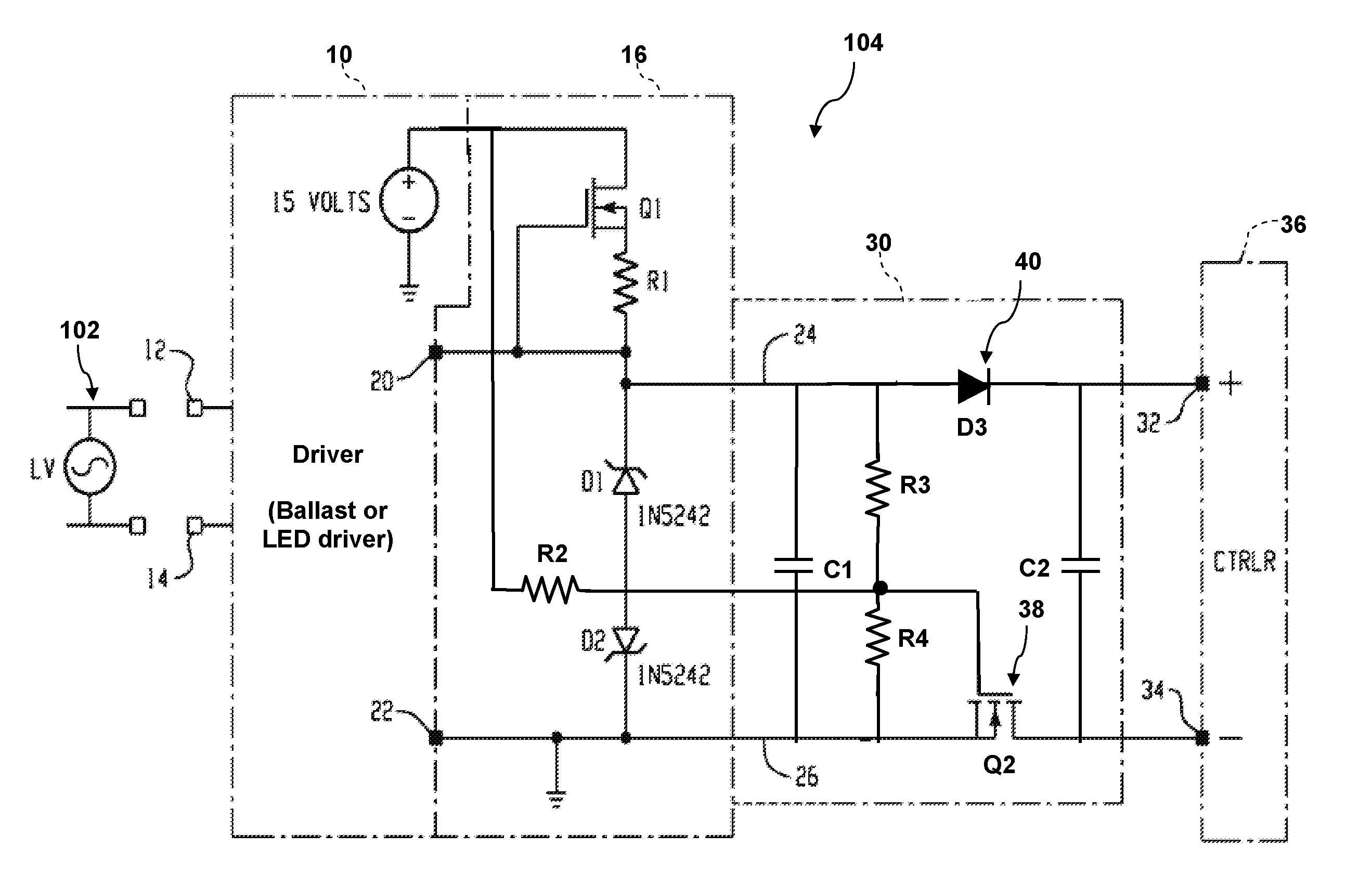
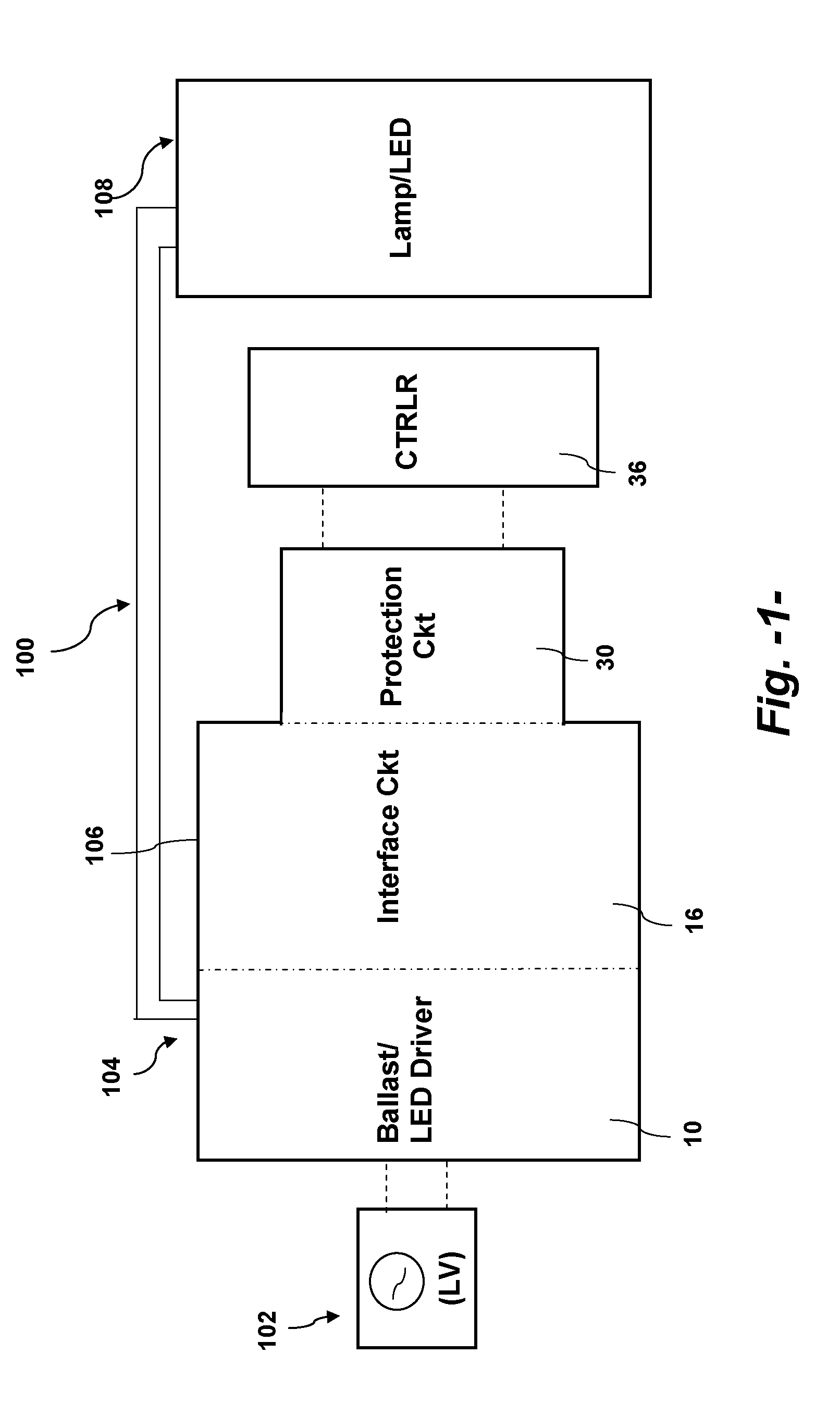
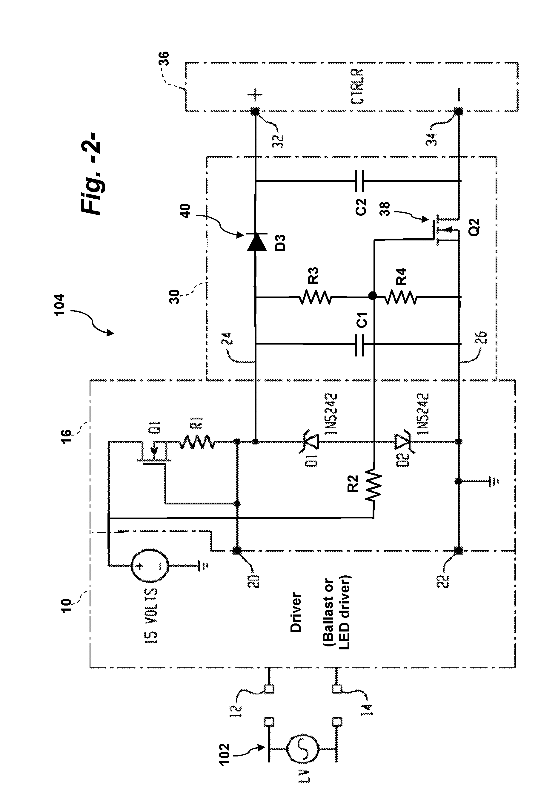
[0022]FIG. 1 is a block diagram of the components of a lamp assembly 100 that may incorporate aspects of the present invention. The lamp assembly 10...


PUM


Abstract

An electronic circuit for use with a lamp controller includes a driver component and a voltage interface circuit powered by the driver component. The interface component delivers a low voltage power signal at a defined operating range via output lines to a downstream controller. A protection circuit is coupled with the voltage interface circuit. The protection circuit in one embodiment has an under-voltage switch disposed in one of the output lines and configured to open at a voltage less than the defined voltage range, and a blocking device disposed in the other output line and configured to block reverse power flow at a voltage above the defined voltage range. In another embodiment, the protection circuit has a first blocking device disposed in either one of the output lines to block reverse power flow to the voltage interface circuit, a PTC device disposed in either one of the output lines, and a second blocking device disposed across the output lines to protect the control circuit from a high voltage reverse polarity condition.

Description

FIELD OF THE INVENTION[0001]The field of the invention relates generally to electronic ballast or LED driver circuitry for use with the ignition of gas discharge lamps or LED general lighting, and more particularly to circuitry that protects the ballast circuitry or LED driver, particularly the dimming circuitry, from an overload condition.BACKGROUND[0002]Presently, it is common practice to house the ballast circuitry for gas discharge lamps in a common housing with a set of electrical leads extending from the housing for connection to a power line, such as a 120 volt / 277 volt single phase AC line, and another set of electrical leads for outputting a low voltage / low amperage signal to the dimming controller. Despite appropriate color coding of each set of leads, miswiring of the leads continues to be a problem in the field wherein the low voltage signal leads intended for connection to the controller are mistakenly connected to a line voltage power source. This miswiring may lead to...

Claims


Application Information

Patent Timeline
Patent Type & Authority Applications(United States)
IPC IPC(8): H05B37/02H05B41/36H05B44/00
CPCH05B41/2851H05B41/2921Y02B20/208Y02B20/186H05B41/2981H02H11/003H05B47/11Y02B20/00H05B47/10H05B47/24Y02B20/30H05B41/285
Inventor YAO, GANG
Owner GE LIGHTING SOLUTIONS LLC
Why Eureka
Try Eureka