Method and device for reporting antenna calibration information and determining antenna calibration factor

a technology of antenna calibration and factor, applied in the field of radio communication, can solve the problems of occupying considerable resources, introducing quantization errors, and mismatching of transmission and reception circuits

Active Publication Date: 2013-02-07
DATANG MOBILE COMM EQUIP CO LTD
View PDF3 Cites 16 Cited by
  • Summary
  • Abstract
  • Description
  • Claims
  • Application Information

AI Technical Summary

Benefits of technology

[0056]Advantageous effects of the invention are as follows.
[0057]In a process of reporting antenna calibration information at the UE side, a UE estimates an equivalent downlink baseband channel from each of a plurality of antennas of a base station to the UE; and the UE determines an amplitude response ρk and a delay value Δk according to the equivalent baseband channel and then reports ρk and Δk to the base station.
[0058]In a process of determining an antenna calibration factor at the base station side, a base station determines an amplitude response λk and a delay value Πk according to a received uplink signal; and then the base station calculates an antenna calibration factor according to ρk and Δk reported from a UE, and λk and Πk.
[0059]Since the UE separates amplitude information and phase information out from channel information and feeds the information back to the base station, and the base station uses the information for calibration, thereby calibrating amplitude and phase concurrently. As can be apparent, the technical solution according to the invention can become less sensitive to a channel estimation error and channel Doppler spreading due to additional pre-processing by the UE.

Problems solved by technology

In a Frequency Division Duplex (FDD) system, the UE feeds the estimated channel information back to the base station over an uplink channel, and this scheme occupies considerable resources of the uplink channel and may introduce a quantization error, etc.
Generally the transmission circuit and the reception circuit are two different circuits, so the transmission circuit and the reception circuit introduce different delays and amplitude gains, in other words, the transmission and reception circuits are mismatched.
Reciprocity of uplink and downlink channels may not exactly holds due to the mismatch of the transmission circuit and the reception circuit.
If the uplink and downlink circuits are mismatched and particularly have different delays, in-phase superimposition of the signals of the respective antennas cannot be ensured, thus lowering the signal to noise ratio of the received signal and deteriorating the performance.
Drawbacks of the prior art lie in as follows: the problem of the calibration scheme 1 lies in that only a phase error but no amplitude error can be calibrated, and an amplitude error may also have a serious influence on the performance; and the calibration scheme 2 can calibrate both a phase error and an amplitude error, but this scheme feeds a quantized synthesis channel back directly to the base station, and an estimation error and a quantization error of the synthesis channel may degrade the precision of calibration.
Furthermore, if the UE has a channel varying with time, a spatially propagating channel measured at the UE may have varied from that measured at the base station, thus causing inaccurate calculation of a calibration coefficient.

Method used


Image

  • Method and device for reporting antenna calibration information and determining antenna calibration factor
  • Method and device for reporting antenna calibration information and determining antenna calibration factor
  • Method and device for reporting antenna calibration information and determining antenna calibration factor

Examples


Embodiment Construction

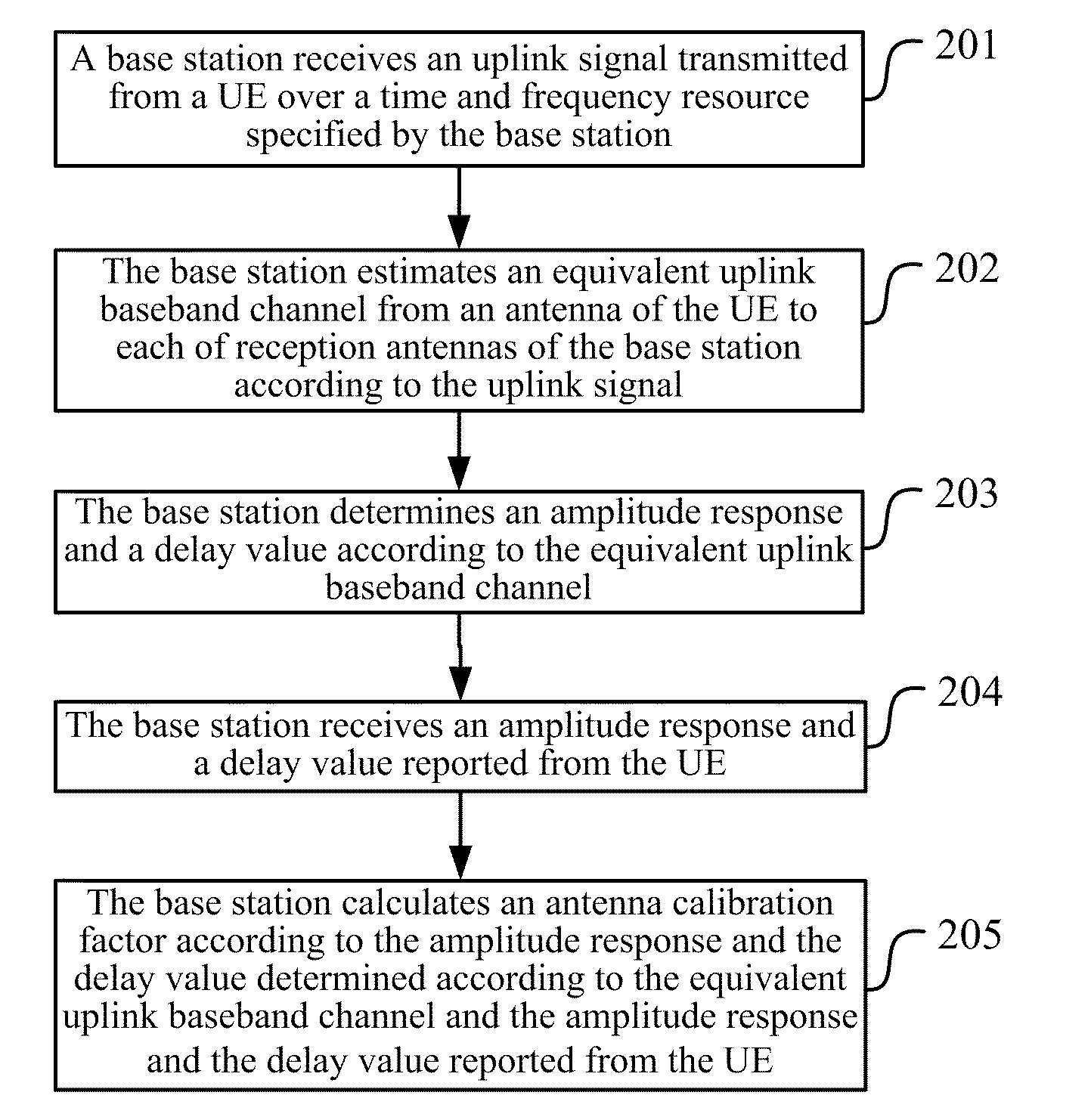
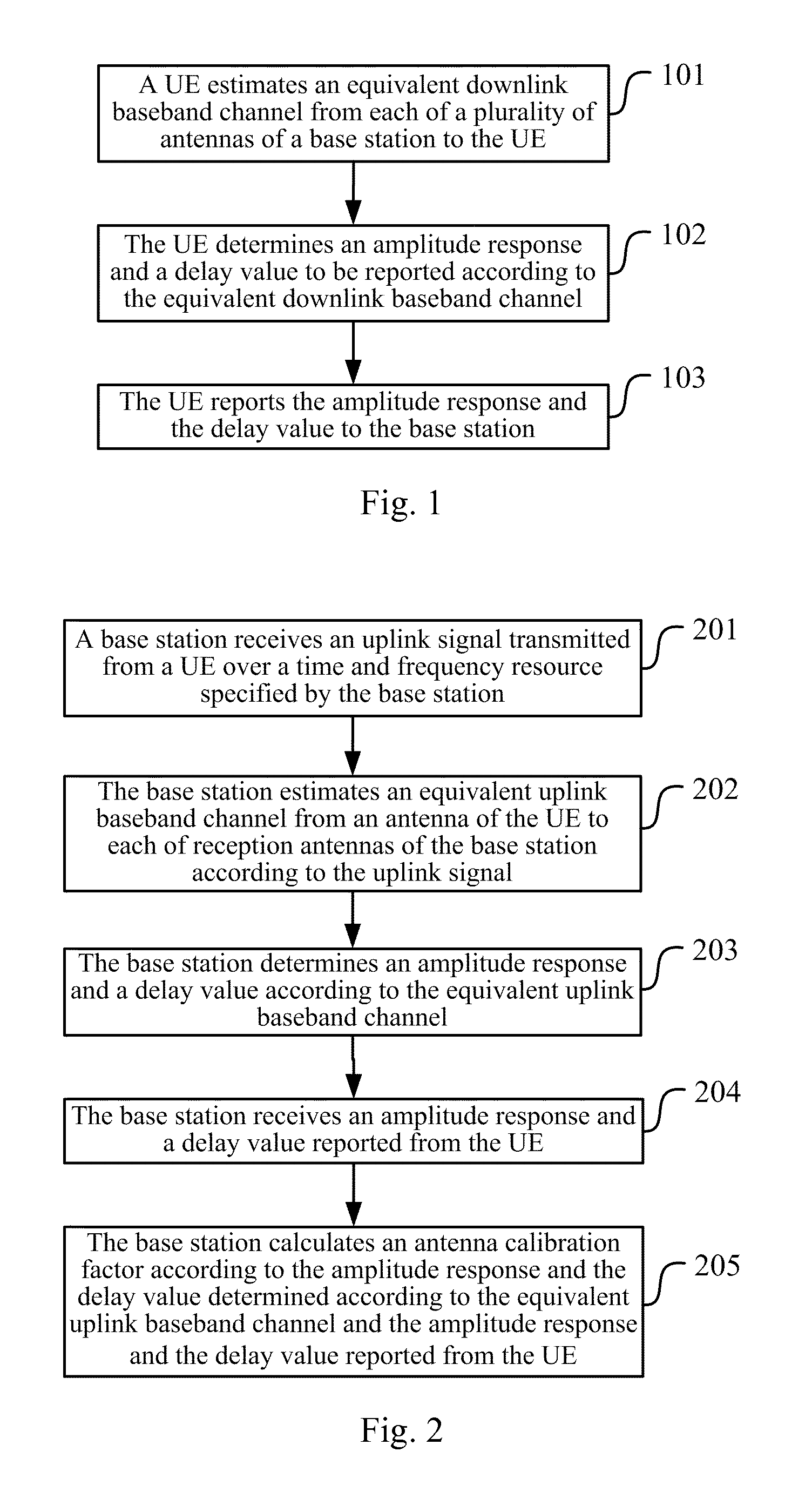
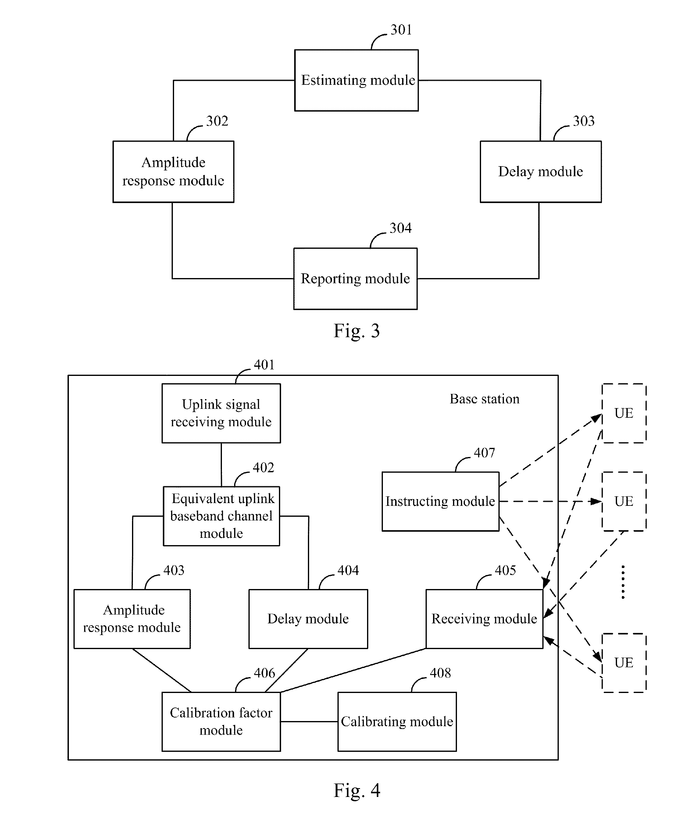
[0064]The multi-antenna technology has become a member of crucial technologies of a next-generation radio communication system, and linear pre-coding / beam-forming in the multi-antenna technology is an effective means to deal with a fading channel, to lower an error probability and to improve the performance of a system. With reciprocity of uplink and downlink channels, a TDD system can obtain information of a downlink channel from a base station to a UE according to information of an uplink channel, from the UE to the base station, estimated by the base station to thereby calculate a pre-coding matrix / a beam-forming weight. However, reciprocity of uplink and downlink channels may not exactly hold in a practical system, and a technical solution according to embodiments of the invention addresses the problem of antenna calibration when reciprocity of uplink and downlink channels does not hold. In the solution, amplitude information and phase information (a delay) are separated out fro...


PUM


Abstract

A method and device for reporting antenna calibration information and determining antenna calibration factor are provided by the present invention. When reporting the antenna calibration information, a user equipment (UE) estimates the downlink equivalent baseband channel from a plurality of antennas of the base station to the UE; according to the equivalent baseband channel, determines the amplitude response and delay value to be reported, and then reports the amplitude response and delay value to the base station. When determining the antenna calibration factor, according to the uplink signal sent by the UE on the base station-directed time-frequency resources, the base station determines the amplitude response and the delay value; according to the amplitude response and delay value reported by the UE and according to the amplitude response and delay value determined by the uplink signal, the base station calculates the antenna calibration factor. Because the UE pre-processing process is added, the sensitivity degrees to the channel estimation error and to the channel Doppler extension are reduced.

Description

[0001]The present application claims priority to Chinese Patent Application No. 201010153539.2, filed with the State Intellectual Property Office of China on Apr. 19, 2010 and entitled “Method and device for reporting antenna calibration information and determining antenna calibration factor”, which is hereby incorporated by reference in its entirety.FIELD OF THE INVENTION[0002]The present invention relates to the field of radio communications and particularly to a method and device for reporting antenna calibration information and determining an antenna calibration factor.BACKGROUND OF THE INVENTION[0003]A Multiple-Input Multiple-Output (MIMO) system refers to a system with a plurality of antennas equipped at both a transmitter and a receiver. A process in the space field is introduced to the MIMO system in addition to traditional processes in the time and frequency domains to thereby further obtain an array process gain and a diversity gain. In the MIMO system, the transmitter can...

Claims


Application Information

Patent Timeline
Patent Type & Authority Applications(United States)
IPC IPC(8): H04W24/10
CPCH04W72/0406H04W72/085H04B7/0626H04L5/0023H04B17/24H04L25/0204H04L25/0224H04B17/12H04B17/21H04L5/0057H04W72/20H04W72/542H04B7/0417
Inventor GAO, QIUBINSUN, SHAOHUIMIAO, DESHANQIN, FEI
Owner DATANG MOBILE COMM EQUIP CO LTD
Why Eureka
Try Eureka