Access point device and communication configuration providing method

a technology of access point device and communication configuration, which is applied in the direction of wireless communication, multiplex communication, frequency-division multiplex, etc., can solve the problem that the configuration technique is not able to set the configuration information in the wireless terminal, the user's manual setup of such configuration information is rather troublesome, and the user may be unfamiliar with the wireless lan

Inactive Publication Date: 2013-02-07
BUFFALO CORP LTD
View PDF4 Cites 18 Cited by
  • Summary
  • Abstract
  • Description
  • Claims
  • Application Information

AI Technical Summary

Benefits of technology

[0046]Changing the ESSID to “!ABC” has the following advantageous effects. When the wireless terminal detects a plurality of access points by passive scan or by active scan, such setting of the changed :ESSID enables this access point AP (virtual port VAP2) to be displayed at the top of a list of detected access points. During the first new setup process described later, the user operating the wireless terminal can thus readily find the access point AP as the connection destination in the list, in order to make a connection between the wireless terminal and the access point AP. This improves the user-friendliness. The changed ESSID is preferably a value that is high on the list. in an application of the list displaying the detected access points in a descending order, the changed ESSID may preferably be a value that is at the top on the list in the descending order.
[0047]The virtual port VAP3 is used for the AOSS process when the CPU 110 detects a press of the easy setup button 160. More specifically, in response to detection of a press of the easy setup button 160, the ESSID of the virtual port VAP3 is changed to, for example, “ESSID-AOSS” or “ESSID-AOSS1”. The changed ESSID is included in the beacon sent by the access point AP. The wireless terminal receiving this beacon is allowed to make a connection with the access point AP (virtual port VAP3) only when the wireless terminal supports AOSS and receives a start command for the AOSS process within a specified time. The AOSS process starts on establishment of a connection between the wireless terminal and the virtual port VAP3.A-3. General Configuration of Wireless Terminal TE2
[0048]FIG. 4 schematically illustrates the configuration of the wireless terminal TE2. As illustrated, the wireless terminal TE2 includes a CPU 210, a flash ROM 220, a RAM 230, a wired LAN interface 240, a wireless communication interface 250 and the easy setup button 260. The CPU 210, the flash ROM 220, the RAM 230, the wired LAN interface 240, the wireless communication interface 250 and the easy setup button 260 are interconnected by a bus.
[0049]The CPU 210 loads and executes a program, such as firmware, stored in the flash ROM 220, on the RAM 230 to control the overall operations of the wireless terminal TE2. The CPU 210 also has the function of performing the second new setup process with the access point AP. The wired LAN interface 240 is an interface for connecting with a wired LAN. According to this embodiment, the wired LAN interface 240 has a wired port. The wired LAN interface 240 is connected with an electronic device without a wireless communication interface. The wireless communication interface 250 is a control circuit for wireless communication in conformity with a wireless LAN standard. The wireless communication interface 250 is controlled by the CPU 210 to implement the functions as the station.
[0050]The easy setup button 260 is operated to give a start command for the second new setup process to the wireless terminal TE2. The interface for receiving a start command is not limited to the button as described previously with respect to the easy setup button 160 of the access point AP.
[0051]The wireless terminal TE3 differs from the wireless terminal TE2 by: (i) replacement of the function of performing the second new setup process of the wireless terminal TE2 with the function of performing the AOSS process or the WPS process; and (ii) replacement of the easy setup button 260 of the wireless terminal TE2 with the easy setup button SW1 operated to give a start command for the AOSS process or the WPS process. Otherwise the wireless terminal TE3 has the similar configuration to that of the wireless terminal TE2.A-4. Connection Setup Process

Problems solved by technology

The user's manual setup of such configuration information is rather troublesome, and the manual setup may be difficult for the user unfamiliar with the wireless LAN.
The auto-configuration technique is thus not able to set the configuration information in the wireless terminal without installation of the special program.

Method used


Image

  • Access point device and communication configuration providing method
  • Access point device and communication configuration providing method
  • Access point device and communication configuration providing method

Examples


first embodiment

A. First Embodiment

[0025]The following describes embodiments of the disclosure with reference to the accompanying drawings.

A-1. General Configuration of Network System 20

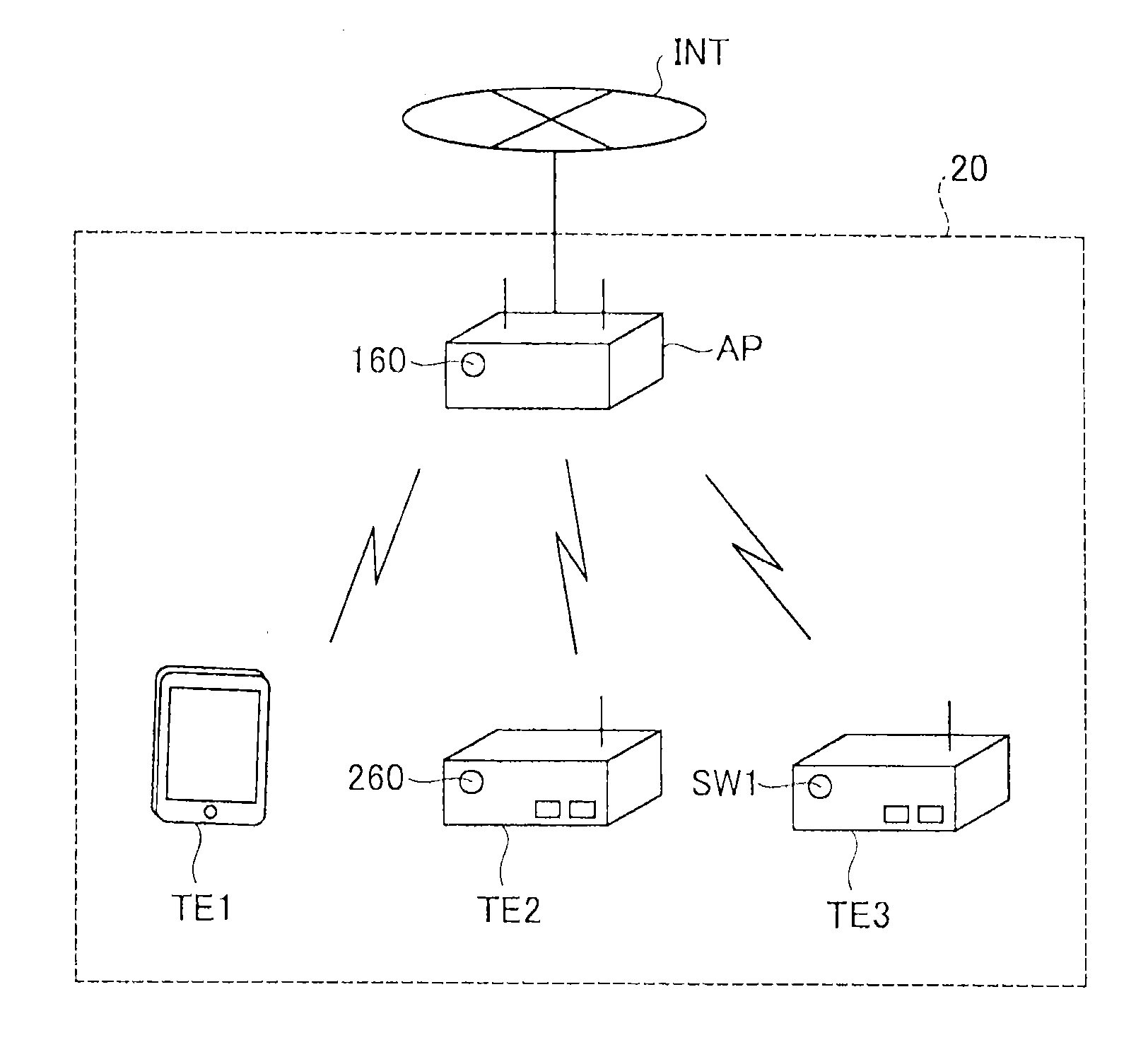
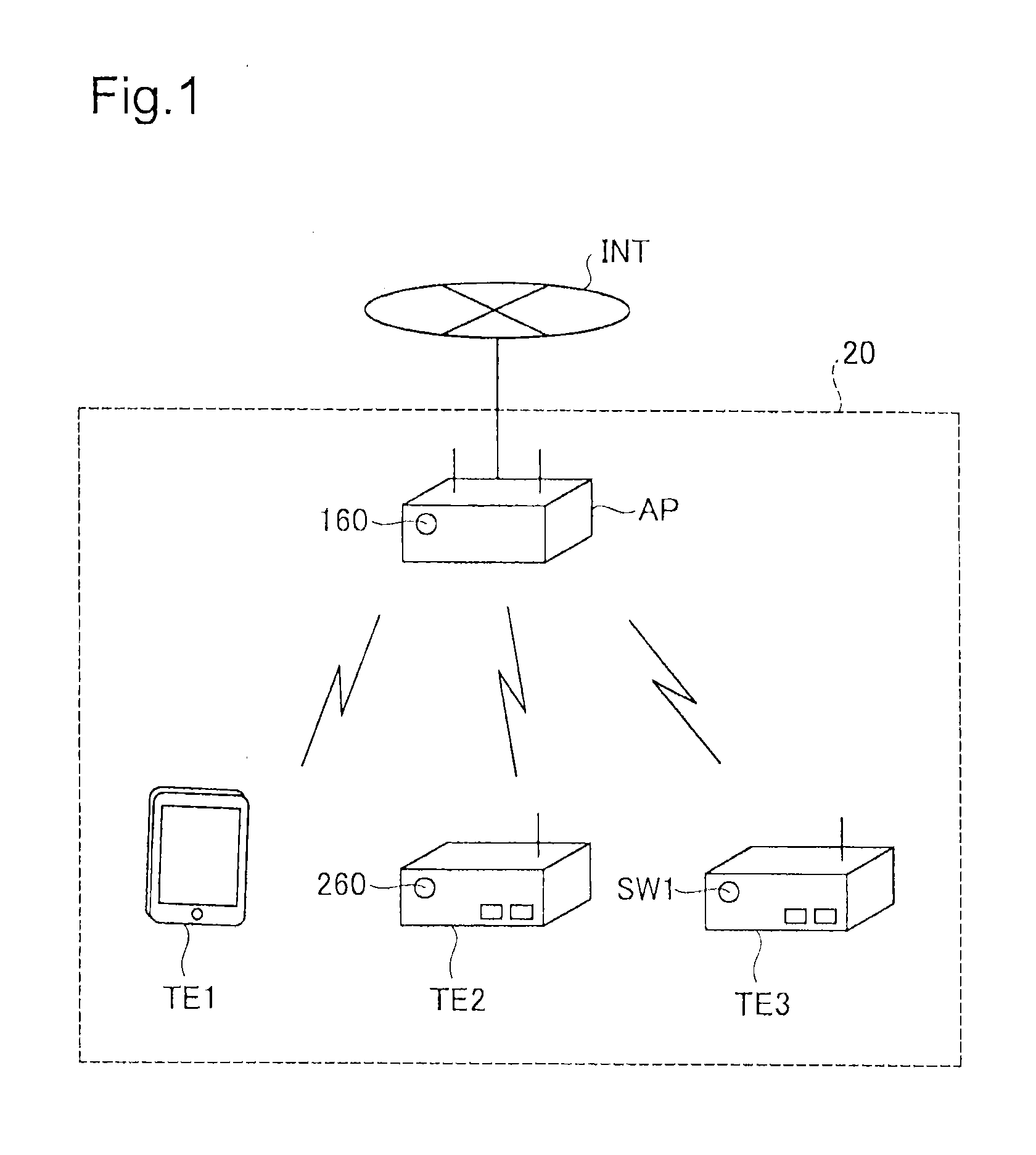
[0026]FIG. 1 illustrates the general configuration of a network system 20 established by using an access point AP as one embodiment of the access point device of the disclosure. According to this embodiment, the network system 20 is implemented as a wireless LAN in conformity with IEEE 802.11 standard. The network system 20 includes the access point AP and wireless terminals TE1 to TE3 as illustrated in FIG. 1.

[0027]The access point AP serves to relay wireless communication of the wireless terminals TE1 to TE3. This access point AP has the router function and is connected to the Internet INT by a network cable. According to this embodiment, the access point AP supports conventionally known AOSS and WPS processes as the auto-configuration to automatically provide the wireless terminal with configuration information f...

second embodiment

B. Second Embodiment

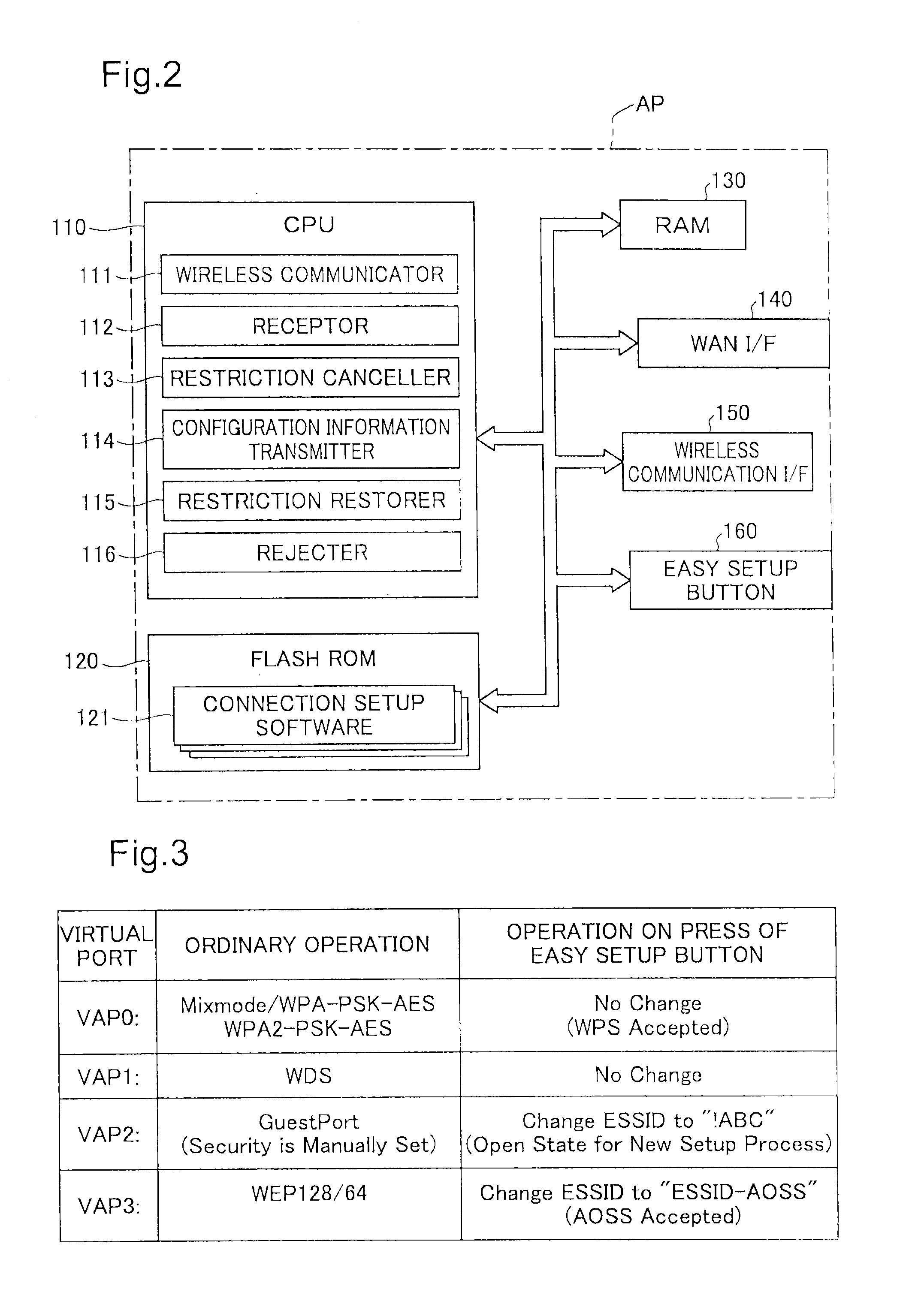
[0086]The following describes a second embodiment of the disclosure. FIG. 9 schematically illustrates the configuration of an access point AP2 according to the second embodiment. The configuration of the access point AP2 is almost similar to that of the access point AP of the first embodiment. The differences of the access point AP2 from the access point AP of the first embodiment are that the CPU 110 does not estimate the validity of the user of the wireless terminal based on the and that the CPU 110 additionally serves as an authenticator 117 as shown in FIG. 9. Otherwise the access point AP2 has the similar configuration to that of the access point AP. The like components in FIG. 9 to those of the first embodiment FIG. 2) are expressed by the like numerical symbols to those of FIG. 2. This access point AP2 employs a different flow of the first new setup process from that of the first embodiment, due to the above differences from the access point AP. Otherwise,...

third embodiment

C. Third Embodiment

[0093]The following describes a third embodiment of the disclosure. FIG. 12 schematically illustrates the configuration of an access point AP3 according to the third embodiment. The configuration of the access point AP3 is almost similar to that of the access point AP of the first embodiment.

[0094]The difference of the access point AP3 from the access point AP of the first embodiment is that connection setup communication software 122 in the form of digital data, in place of the connection setup software 121, is recorded in the flash ROM 120 as shown in FIG. 12. The connection setup communication software 122 is a program for a processing flow executed by the wireless terminal during the second new setup process described above. Otherwise the access point AP3 has the similar configuration to that of the access point AP. The like components in FIG. 12 to those of the first embodiment (FIG. 2) are expressed by the like numerical symbols to those of FIG. 2. This acce...


PUM


Abstract

An access point enables wireless communication in a restricted state where a connection object is limited to less than full functionality. The access point change, in response to the specific instruction being received, changes the restricted state to a non-restricted state where the connection object is not limited, when receiving a specific instruction from a user. The access point sends configuration information for specified security communication between a wireless terminal and the access point or a setup program executed to cause the wireless terminal to obtain the configuration information, to the wireless terminal, when receiving an access from the wireless terminal establishing connection with the access point, in the non-restricted state. The access point returns from the non-restricted state to the restricted state on the occurrence of a specified event. This communication configuration technique is highly versatile and enables the configuration information to be readily set in the wireless terminal.

Description

CROSS-REFERENCE TO RELATED APPLICATIONS[0001]This application claims the benefit of priority under 35 U.S.C. §119 to Japanese Patent Application No. 2011-170975 filed on Aug. 4, 2011, which is hereby incorporated by reference in its entirety and for all purposes.BACKGROUND OF THE INVENTION[0002]1. Field of the Invention[0003]The disclosure relates to communication configuration technique for wireless communication.[0004]2. Description of the Related Art[0005]In order to perform security communication ensuring security in a wireless LAN, it is required to set configuration information including encryption settings and authentication information in both an access point and a wireless terminal (station). The user's manual setup of such configuration information is rather troublesome, and the manual setup may be difficult for the user unfamiliar with the wireless LAN. The following technique (hereinafter referred to as “auto-configuration technique”) has accordingly been developed. This...

Claims


Application Information

Patent Timeline
Patent Type & Authority Applications(United States)
IPC IPC(8): H04W88/00
CPCH04W76/02H04L63/108H04W88/08H04W12/06H04W24/02H04W12/04H04W76/10H04W12/50
Inventor ISHII, HIDEKIICHIKAWA, GOKIHABA, YOSHIFUMI
Owner BUFFALO CORP LTD
Why Eureka
Try Eureka