Multi-cell battery

Inactive Publication Date: 2013-02-07
ONEPOINT SOLUTIONS
View PDF2 Cites 3 Cited by
  • Summary
  • Abstract
  • Description
  • Claims
  • Application Information

AI Technical Summary

Benefits of technology

[0018]The improved heat production characteristic of batteries according to the invention is an important and unexpected advantage. Excess heat production is highly undesirable, and can result in the need for expensive cooling, or even battery failure. A control battery and a battery according to this invention (the same as described in the above test) were tested as follows. The control battery was subjected to a 405 amp load, and the battery temperature rose by 38° F. The battery according to this invention was subjected to a 540 amp load, and the battery temperature rose 20° F. Thus, the battery according to this invention carried a 33% greater load, but generated 47% less heat than an otherwise identical battery.
[0019]The improv

Problems solved by technology

However, for a multi-cellular battery, this

Method used


Image

  • Multi-cell battery
  • Multi-cell battery
  • Multi-cell battery

Examples


first embodiment

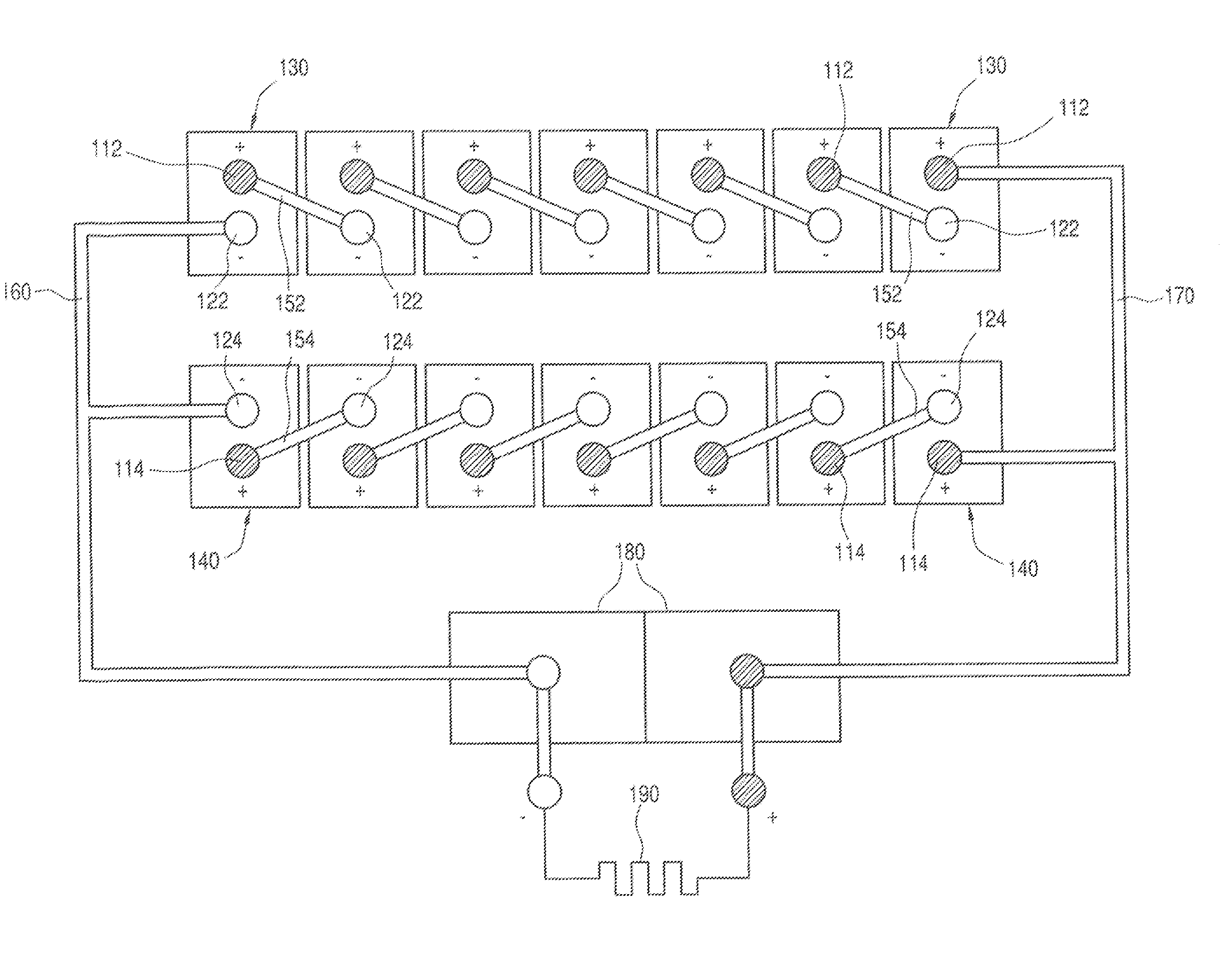
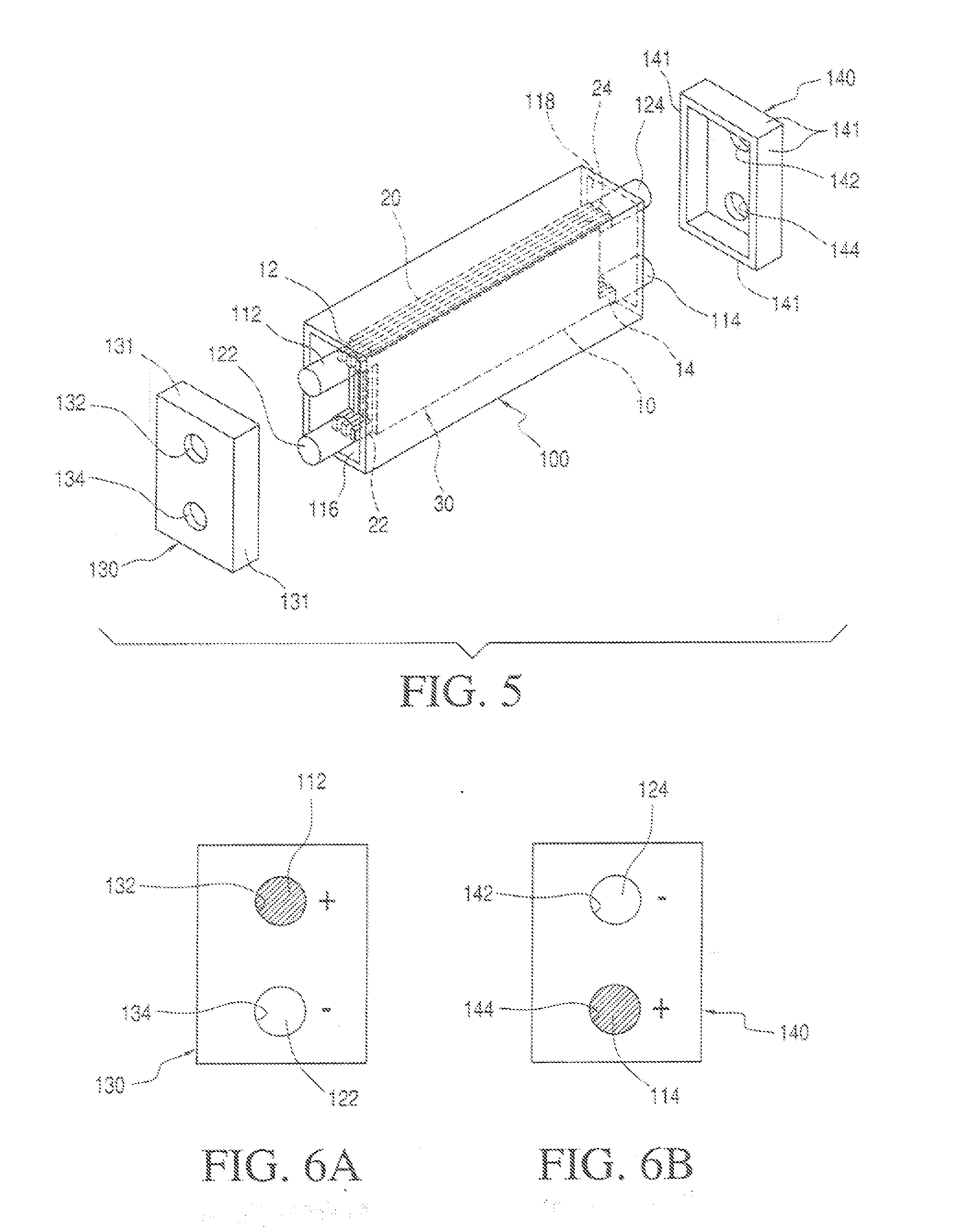
[0039]In FIG. 5, an exploded perspective view of the first embodiment is shown. A container 100 is a rectangular tube open at two ends and can be formed by an extrusion process. The plate element 30 is loaded inside the container 100 through either of the two open ends and is composed of a plurality of positive plates 10 and a plurality of negative plates 20. Upper positive tabs 12 of the positive plates 10 are connected to an upper positive post 112 through one short open end 116 of the container 100 while lower positive tabs 14 of the positive plate 10 are connected to a lower positive post 114 through an opposite short open end 118 of the container 100. The lower negative tabs 22 of the negative plates 20 are connected to a lower negative post 122 through the one short open end 116 of the container 100 while the upper negative tabs 24 of the negative plates 20 are connected to an upper negative post 124 through the opposite short open end 118 of the container 100. At the open end...

second embodiment

[0043]FIG. 8A is a perspective view of the positive or negative cross strap assembly 270 or 260 of the invention.

[0044]FIG. 8B is a cross section view of the positive post 212 and 214 or negative posts 222 and 224 and plastic seals 215 with the positive or negative cross strap 270 or 260 imbedded in the positive posts 212 and 214 or negative posts 222 and 224.

[0045]FIG. 8C is a perspective front view of a multi-cell container 200 with nothing installed. Holes YY and XX provide electrical access for the positive cross strap assembly 270 of FIG. 8A to positive plates 210. Holes PP and ZZ provide electrical access for the negative cross strap assembly 260 of FIG. 8A to negative plates 220. After the container 200 is installed into the steel jacket 275 of FIG. 8D the positive and negative cross strap assemblies 270 and 260FIG. 8A are positioned in steel jack cut outs 276 over holes XX, YY, ZZ and PP, and then the plastic seals are heat sealed to the container 200.

[0046]FIG. 8E is a top ...


PUM


Abstract

A battery with improved power output, reduced heat production and longer performance under constant discharge is disclosed.

Description

CROSS-REFERENCE TO RELATED APPLICATIONS[0001]This disclosure is related to U.S. patent application Ser. No. 12 / 926,013 filed Oct. 21, 2010, for a “Battery” in the name of Darwin D. Delans and assigned to OnePoint Solutions, L.L.C. of Philadelphia, Pa. This related application matured out of U.S. Provisional Patent Application Ser. No. 61 / 279,350 filed on Oct. 21, 2009.STATEMENT REGARDING FEDERALLY SPONSORED RESEARCH OR DEVELOPMENT[0002]This invention is not the subject of any federally sponsored research or development.STATEMENT REGARDING JOINT RESEARCH AGREEMENTS[0003]The invention discussed in this disclosure was not and is not the result of any joint public or private research agreements.BACKGROUND OF THE INVENTION[0004](1) Field of the Invention[0005]The technical field of the art to which the invention pertains is electrochemical batteries in general and batteries with external cross straps in particular.[0006](2) Description of the Related Art[0007]Mostly all modern single and...

Claims


Application Information

Patent Timeline
IPC IPC(8): H01M2/20H01M50/51H01M50/516H01M50/548
CPCH01M2/30H01M2/202Y02E60/10H01M50/51H01M50/516H01M50/548
Inventor DELANS, DARWIN D.
Owner ONEPOINT SOLUTIONS
Why Eureka
Try Eureka