Thin-type heat pipe structure

a heat pipe and thin-type technology, applied in the field of thin-type heat pipes, can solve the problems of small space provided by heat pipes and rapid drying of heat receiving areas

Inactive Publication Date: 2013-02-14
COOLER MASTER DEVELOPMENT CORP
View PDF6 Cites 32 Cited by
  • Summary
  • Abstract
  • Description
  • Claims
  • Application Information

AI Technical Summary

Benefits of technology

[0007]The present invention provides a thin-type heat pipe structure. By staking and arranging several capillary structures, the present invention speeds up inner air's outflow and inner liquid's backflow.

Problems solved by technology

However, because electronic products generally have to be light, thin, short, and small, only a small space can be provided to heat pipes.
However, conventional heat pipes are round and hence are not suitable for electronic products that should be as thin as possible.
If the density of the capillary structure is high, the inner air will flow out swiftly when receiving heat, causing the heat receiving area to dry out quickly.
If the density of the capillary structure is low, the heat pipe will be inefficient in conducting heat, and resulting in some problems that must be resolved.

Method used


Image

  • Thin-type heat pipe structure
  • Thin-type heat pipe structure
  • Thin-type heat pipe structure

Examples


Embodiment Construction

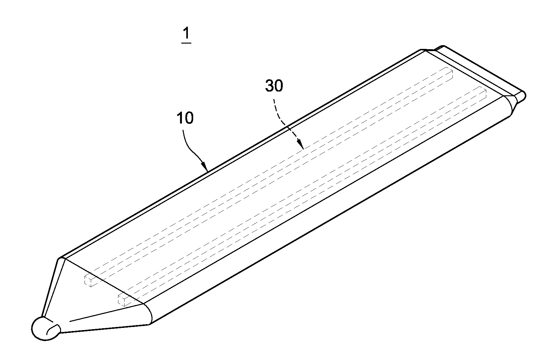
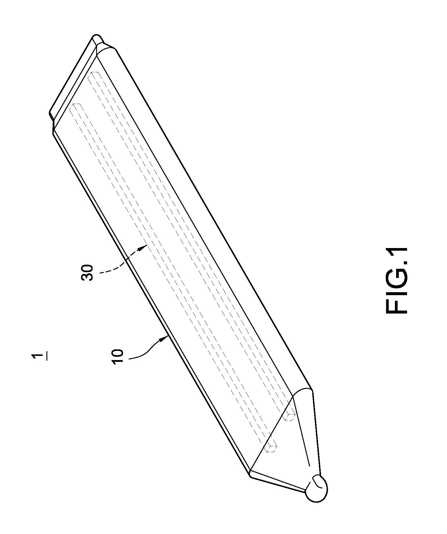
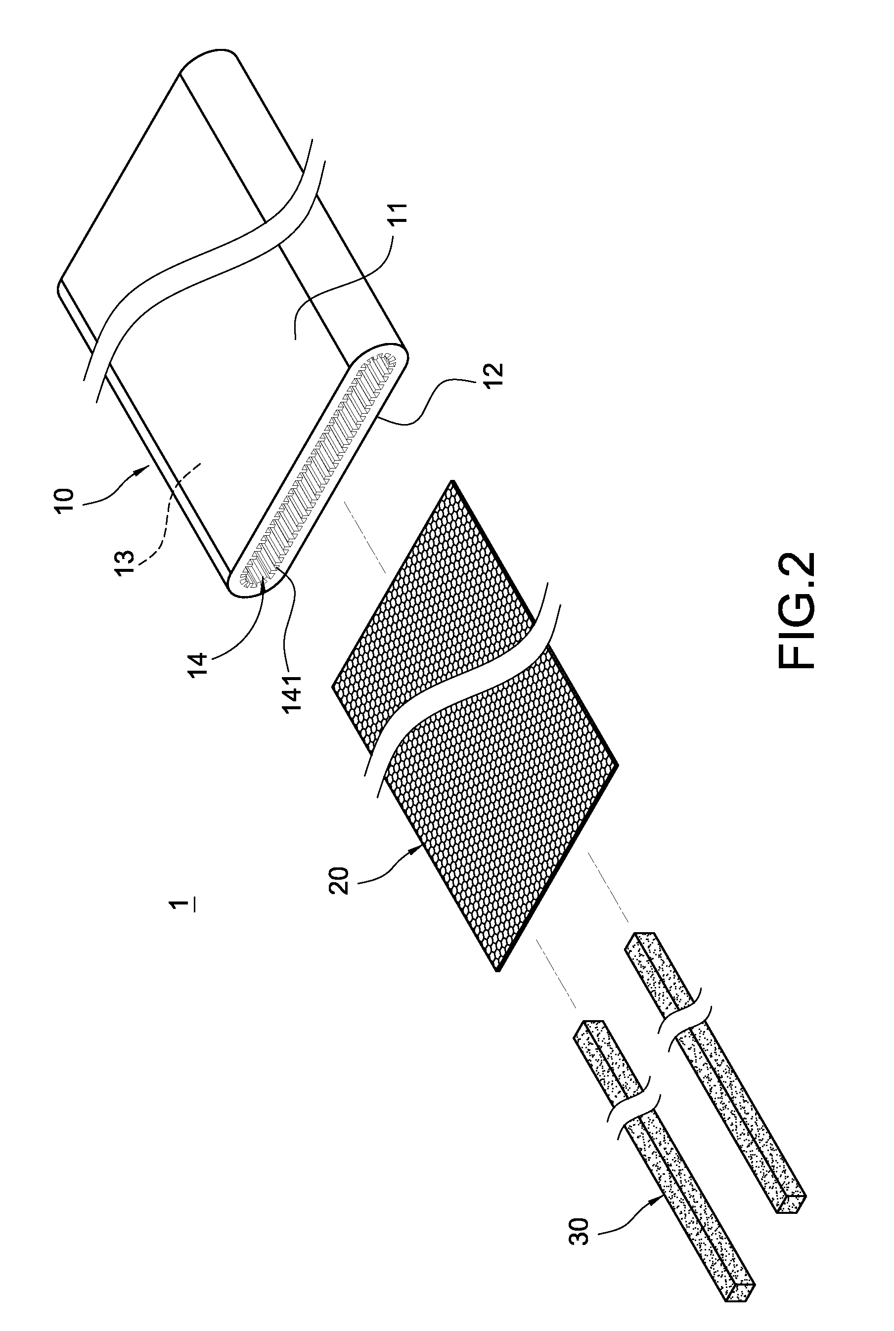
[0016]Please refer to FIG. 1 to FIG. 4. The present invention provides a thin-type heat pipe structure. The thin-type heat pipe 1 mainly includes a flat pipe 10, a second capillary structure 20, a third capillary structure 30, and a working fluid 40.

[0017]The flat pipe 10 is made up of materials with good heat conductivity and good ductility, such as copper or copper alloy. It is formed by pressing a round pipe and hence has a flat shape. In this embodiment, the pipe 10 is a stripe formed by an upper board 11 and a lower board 12 that correspond to each other. Each of the upper and lower boards 11 and 12 is formed by a lateral flat section and a longitudinal curved section that extends from the lateral flat section. As shown in FIG. 2, the lateral flat section and the longitudinal curved section form a shape that is similar to the letter ‘J,’ and are sealed up on an end of the pipe 10 through soldering. A hollow containing chamber 13 exists in between the upper and lower boards 11 a...


PUM


Abstract

A thin-type heat pipe structure includes a flat pipe, a second capillary structure, a third capillary structure, and a working fluid. The flat pipe has two boards and a containing chamber. A first capillary structure is set on the inner surface of the boards. The second capillary structure is contained in the containing chamber and covers a part of the first capillary structure. The third capillary structure is a stripe, contained in the containing chamber and clipped between the second capillary structure and another part of the first capillary structure. The working fluid is filled in the containing chamber. The overall design speeds up inner air's outflow and inner liquid's backflow.

Description

BACKGROUND[0001]1. Technical Field[0002]The present invention generally relates to a heat pipe, and more particularly, to a thin-type heat pipe structure that is used to guide heat generated by an electronic heat source.[0003]2. Related Art[0004]The exacerbating problems caused by electronic heat sources can be resolved by using heat pipes to conduct or dissipate heat generated by electronic products. Replacing cooling structures formed by cooling fins with heat pipes seems to be the future development trend. However, because electronic products generally have to be light, thin, short, and small, only a small space can be provided to heat pipes. As a result, the industry desires to have new heat pipe designs to resolve the problem.[0005]A conventional heat pipe generally includes a round pipe, a capillary structure, and a working fluid. Inside the round pipe there is a containing chamber. The capillary structure is set inside the containing chamber and stuck to the inner surface of ...

Claims


Application Information

Patent Timeline
Patent Type & Authority Applications(United States)
IPC IPC(8): F28D15/04
CPCF28D15/046F28D15/0233
Inventor CHEN, CHANG-YINLIU, LEI-LEI
Owner COOLER MASTER DEVELOPMENT CORP
Why Eureka
Try Eureka