Rotary Shoe Direct Fluid Flow System

a technology of fluid flow and rotary shoe, which is applied in the direction of fluid removal, drilling accessories, borehole/well accessories, etc., can solve the problems of inability to cool the cutting structure, inability to remove debris, and the inability to use the annular path between the mandrel and the inside wall of the shoe, so as to improve the cooling effect, reduce the loss of fluid to the formation, and remove debris.

Inactive Publication Date: 2013-02-14
BAKER HUGHES INC
View PDF5 Cites 2 Cited by
  • Summary
  • Abstract
  • Description
  • Claims
  • Application Information

AI Technical Summary

Benefits of technology

[0006]The circulation system for a rotary shoe features a fluid diversion to a peripheral zone from which the flow is directed by tubes or housing bores to the vicinity of the cutting structure to improve cooling and removal of debris. Some of the fluid is directed straight through into the mandrel or body of the tool being milled. If the formation below is at low pressure a packer cup is added to the grip tool attached to the shoe at one end and to the fish at the other end. A swivel is used to prevent the packer cup rotation. Fluid diverted by the packer cup comes up out of the mandrel and into an annular space between the mandrel and the inner wall of the shoe and out from under the shoe by flowing past the cutters. Fluid loss to the formation is minimized and cooling and cutting removal is enhanced.

Problems solved by technology

More recently when components have been fabricated or formed from much harder metals the technique of depending on the annular path between the mandrel and the inside wall of the shoe proved more troubling due to the longer mill times and the additional heat generated from trying to mill the harder materials.
Such fluid stream that was intended to come back to the area where the cutters are mounted through the annular space between the mandrel and the inner wall of the rotating shoe could be lost downhole and therefore would be unavailable for cooling the cutting structures and removal of debris.

Method used


Image

  • Rotary Shoe Direct Fluid Flow System
  • Rotary Shoe Direct Fluid Flow System
  • Rotary Shoe Direct Fluid Flow System

Examples


Embodiment Construction

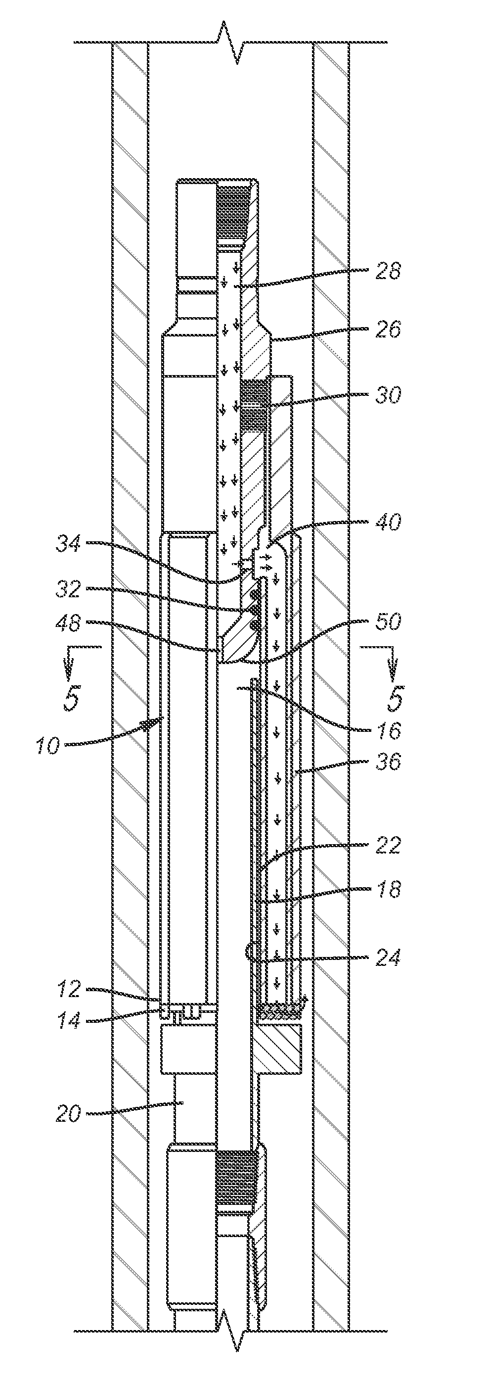
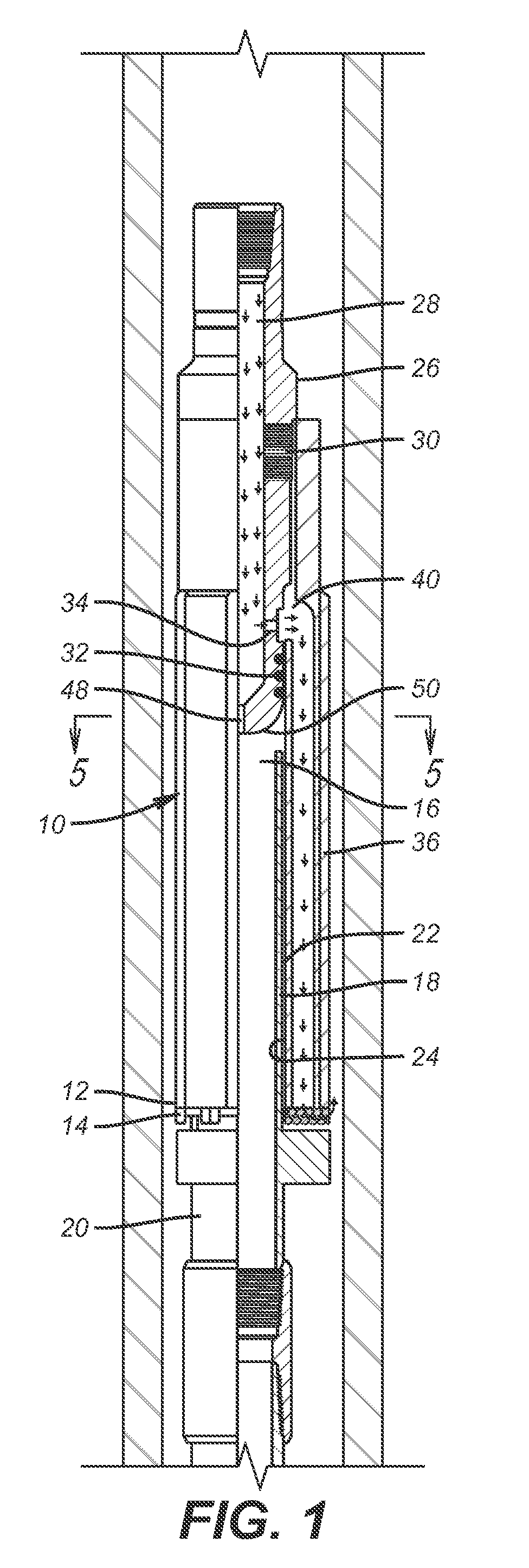
[0017]The rotary mill or shoe 10 has a lower end 12 where the cutters 14 are located on the periphery in a known manner. There is an internal open area 16 through which the mandrel 18 of the packer 20 can enter as the milling progresses. An annular gap 22 is formed between the mandrel 18 and the inner wall 24 of the shoe 10. Flow is delivered from the surface through a string that is not shown and into flow distributor 26 that has a central passage 28. Seal assemblies 30 and 32 straddle one or more lateral openings 34. Shoe 10 has a body or wall 36 that is shown in section in alternative embodiments in FIGS. 5 and 6. In FIG. 5 there are tubes 38 that start at annular space 40 shown in FIG. 1 and terminate at a lower end near the cutters 14. Alternatively, in FIG. 5 the body 36 has drilled axial holes 42 to conduct cooling fluid that removes the cuttings from the location of the cutters 14. As before the drilled holes start at annular space 40 and continue axially to the location of ...


PUM


Abstract

The circulation system for a rotary shoe features a fluid diversion to a peripheral zone from which the flow is directed by tubes or housing bores to the vicinity of the cutting structure to improve cooling and removal of debris. Some of the fluid is directed straight through into the mandrel of the tool being milled. If the formation below is at low pressure a packer cup is added to the grip tool attached to the shoe at one end and to the fish at the other end. A swivel is used to prevent the packer cup rotation. Fluid diverted by the packer cup comes up out of the mandrel and into an annular space between the mandrel and the inner wall of the shoe and out from under the shoe by flowing past the cutters. Fluid loss to the formation is minimized and cooling and cutting removal is enhanced.

Description

FIELD OF THE INVENTION[0001]The field of the invention is subterranean milling and more particularly where the mill washes over the stuck object such as a packer and has a fluid distribution system directed at the cutting structure with a seal option in the packer mandrel to control fluid loss during milling.BACKGROUND OF THE INVENTION[0002]Milling shoes are mills with peripheral cutters that descend over an object to be milled such as a packer as the cutting progresses. The cutting structure takes out the packer seal assembly as well as any slip assembly and extrusion barriers. The packer mandrel, or innermost structural member that supports a packer sealing element and slip assembly and which can be a part of an assembly of parts generally referred to as the packer body, is straddled by the hollow center of the shoe as the shoe descends as the cutting progresses, as shown in FIGS. 7-10. Pumped fluid to cool the cutting structures is delivered through the hollow core of the shoe as...

Claims


Application Information

Patent Timeline
Patent Type & Authority Applications(United States)
IPC IPC(8): E21B43/11
CPCE21B29/00E21B10/60E21B10/26
Inventor BLAIR, STEVEN G.HARMON, STEPHEN K.
Owner BAKER HUGHES INC
Why Eureka
Try Eureka