
Electric vehicle and roadway power system therefore

a technology of electric vehicles and power systems, applied in power rails, rail devices, transportation and packaging, etc., can solve the problems of reducing the range of electric vehicles, limiting the distance between battery charges, and using a combustion engine,

Inactive Publication Date: 2013-02-14
AGUILAR JORGE
View PDF3 Cites 34 Cited by
  • Summary
  • Abstract
  • Description
  • Claims
  • Application Information

AI Technical Summary

Benefits of technology

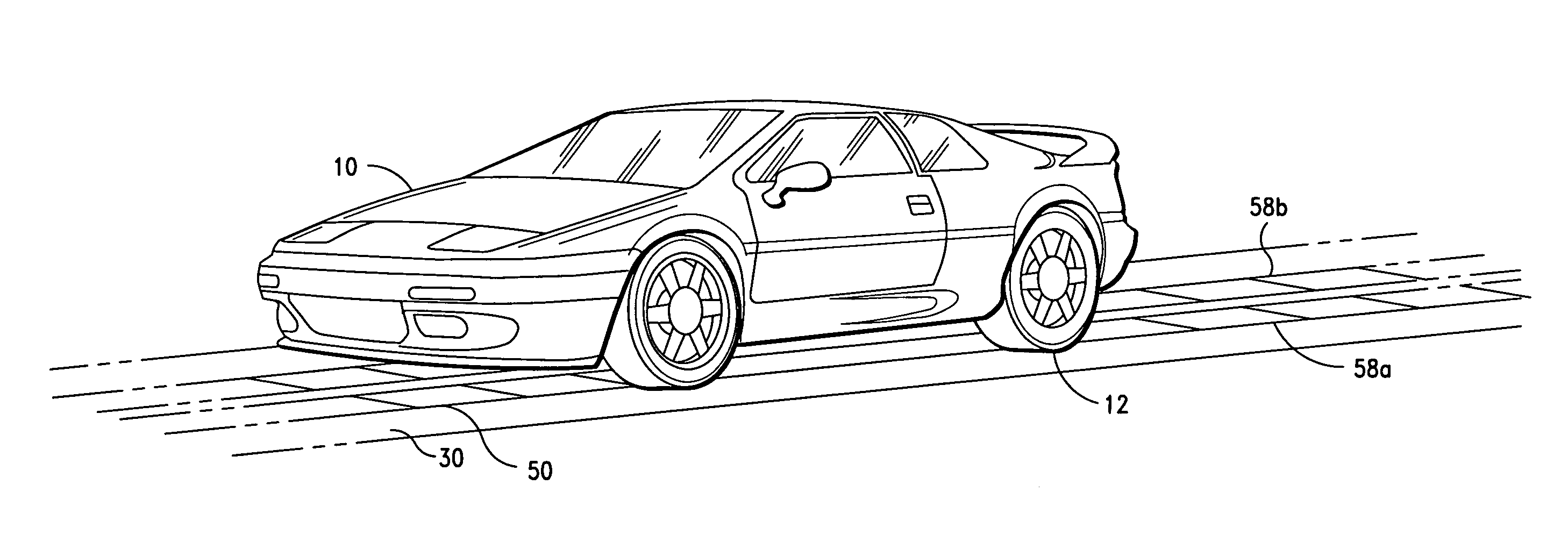
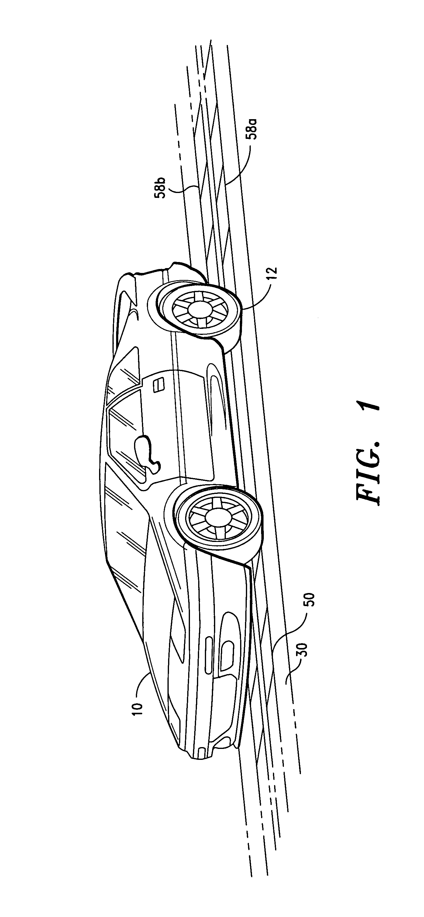
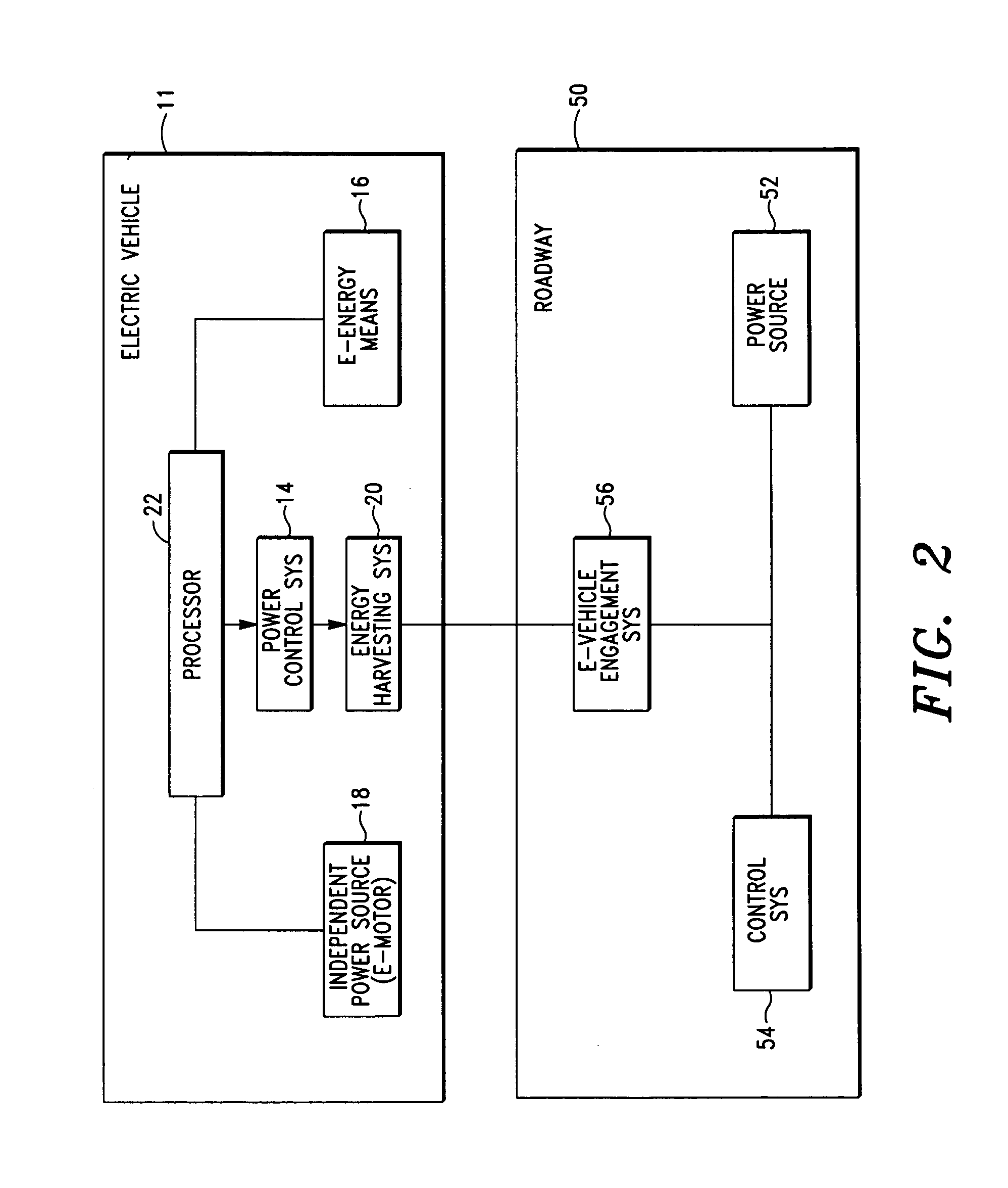
The invention is about an improved power system for electric vehicles. It uses segmented, parallel electrically-conducting surfaces that are only powered when an electric vehicle is on the road and within a controlled area. This system is more efficient and reliable than previous methods.

Problems solved by technology

Due to the limitations of battery capacity, a pure battery-operated vehicle typically has to reserve a significant portion of its weight for the battery pack.
A pure battery-operated vehicle also has a significant limitation in the distance it can travel between battery charges.
There are several well known drawbacks and disadvantages associated with hybrid vehicles.
Among the drawbacks is the use of a combustion engine and the weight and emissions associated therewith.
Hybrid vehicles are also typically quite expensive.
There are several significant drawbacks and disadvantages associated with the noted electric vehicle and roadway system.
A major drawback is that recessed strips are susceptible to short circuits due to water, ice and any conducting foreign objects on the road.
Further, since the strips are continuously energized, the roadway power system poses a serious risk to foot traffic.
This requires the plates to be accessible outside of the vehicle, which similarly poses a serious risk to foot traffic.
There are several significant drawbacks and disadvantages associated with the noted electric vehicle and roadway system.
A major drawback is that the vehicle employs a very complicated electromagnetic system to obtain power from the roadway system.
A further drawback of noted electric vehicle and roadway system is that the energy that can be transferred to the vehicle is significantly limited.
Indeed, in some instances, such as a steep terrain, the magnitude of the power that is required to power the vehicle may be insufficient.

Method used


Image

  • Electric vehicle and roadway power system therefore
  • Electric vehicle and roadway power system therefore
  • Electric vehicle and roadway power system therefore

Examples


Embodiment Construction

[0043]Before describing the present invention in detail, it is to be understood that this invention is not limited to particularly exemplified apparatus, systems, structures or methods as such may, of course, vary. Thus, although a number of apparatus, systems and methods similar or equivalent to those described herein can be used in the practice of the present invention, the preferred apparatus, systems, structures and methods are described herein.

[0044]It is also to be understood that the terminology used herein is for the purpose of describing particular embodiments of the invention only and is not intended to be limiting.

[0045]Unless defined otherwise, all technical and scientific terms used herein have the same meaning as commonly understood by one having ordinary skill in the art to which the invention pertains.

[0046]Further, all publications, patents and patent applications cited herein, whether supra or infra, are hereby incorporated by reference in their entirety.

[0047]Fina...


PUM


Abstract

An electrical vehicle transportation system that includes a powered roadway system having electrically conductive roadway segments that are engageable to a roadway surface, and an electrical vehicle having a control system and an energy harvesting system, the vehicle control system being programmed to energize roadway segments disposed within a defined vehicle envelope and de-energize the roadway segments prior to transitioning outside of the vehicle envelope when the vehicle is traversing the roadway.

Description

CROSS-REFERENCE TO RELATED APPLICATIONS[0001]This application claims the benefit of U.S. Provisional Application No. 61 / 574,986, filed Aug. 12, 2011.FIELD OF THE INVENTION[0002]The present invention relates to electrically operated transportation vehicle systems. More particularly, the present invention relates to an improved electrically operated transportation vehicle and roadway power system for supplying power to the electric vehicle.BACKGROUND OF THE INVENTION[0003]As is well known in the art, there are several types of electrically operated vehicles. The first type is heavily dependent on an outside power source for functional operation. One well-known example comprises electrically powered public transportation vehicles, such as a trolley or bus, which receive electrical power through overhead electrical cables. The noted vehicles typically have a very limited battery pack and, hence, are generally confined to region(s) proximate power cables.[0004]The second type of electric...

Claims


Application Information

Patent Timeline
Patent Type & Authority Applications(United States)
IPC IPC(8): B60M1/08
CPCB60L5/36B60L2200/26B60M7/003B60M1/08B60L53/14B60L53/36B60L53/67Y02T10/70Y02T10/7072Y02T90/12Y02T90/14Y02T90/16
Inventor AGUILAR, JORGE
Owner AGUILAR JORGE
Learn More