Winding Machine and Method for Controlling the Winding Machine

a winding machine and winding technology, applied in the direction of filament handling, tension measurement, web handling, etc., can solve the problems of changing the length changing the tension of the winding material in the feeding path, and changing the dependence of the winding material tension, so as to reduce the tension of the winding material and/or of the deflection, increase the pressing force, and reduce the effect of the deflection

Inactive Publication Date: 2013-02-14
GEORG SAHM GMBH & CO KG
View PDF2 Cites 4 Cited by
  • Summary
  • Abstract
  • Description
  • Claims
  • Application Information

AI Technical Summary

Benefits of technology

[0049]According to another embodiment basing on the use of several pressure rollers, an adjustment of different tensions occurring in the feeding paths of the winding material to the different wound packages is effected by moving a pressure roller in radial direction relative to the rotational axis of the spindle towards the spindle for increasing the pressing force and for decreasing the tension of the winding material and / or of the deflection of a dancer roller in the corresponding feeding path. The other pressure roller is moved in radial direction relative to the rotational axis of the spindle away from the spindle for decreasing the pressing force and for increasing the tension of the winding material and / or of the deflection of the dancer roller in the corresponding feeding path. It is possible but not required that in addition to these measures the rotational speed of the wound packages is controlled.

Problems solved by technology

If the velocity of feeding the winding material from the supply station differs from the winding speed at the winding machine, this results in a change in the length of the winding material in the feeding path.
EP 1 190 974 B1 describes the problem that a slow or inaccurate control of the rotational speed of the wound package results in a changed length of the winding material in the feeding path.
A related undesired result is that the tension in the winding material changes in dependence on the difference between the feeding velocity of the winding material by the supply station and the velocity of taking off the winding material by the wound package.
However, in practice in the two parallel feeding paths different tensions and tension changes often occur.
If an adjustment of the rotational speed of one wound package was carried out in order to counteract a change of the winding material in the feeding path to this wound package, this would directly have the undesired result that the tension of the winding material in the parallel feeding path to the other wound package also changes.
However, the pivoting of the dancer arm against the loading of a spring might also results in a change of the tension of the winding material wherein the magnitude of this change depends on the spring stiffness.
However, also for the use of the pneumatic cylinder an undesired change of the tension of the winding material is effected, if the length of the winding material exceeds the maximum displacement of the dancer roller, so that the dancer roller has reached an end position wherein no further compensating movement is possible.
However, a variation of the slip might be undesired, since especially an increase of the slip might result in an undefined driving state of the wound package and fluctuations of i. This might result for example in a less precise winding pattern.b) For a conical form of the wound package or the pressure roller, a pivoting of the wound package or the pressure roller might effect that the frictional contact between the wound package and the pressure roller is moved to a different diameter of the conical wound package or of the conical pressure roller.
However, this mechanism necessarily requires the use of a conical wound package or a conical pressure roller.

Method used


Image

  • Winding Machine and Method for Controlling the Winding Machine
  • Winding Machine and Method for Controlling the Winding Machine
  • Winding Machine and Method for Controlling the Winding Machine

Examples


Embodiment Construction

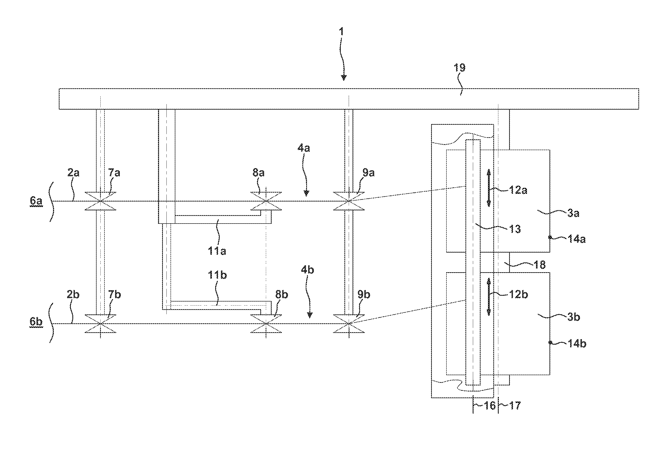
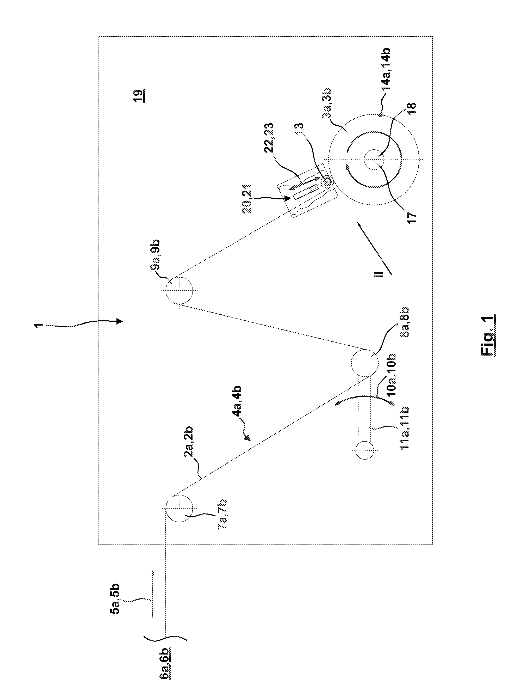
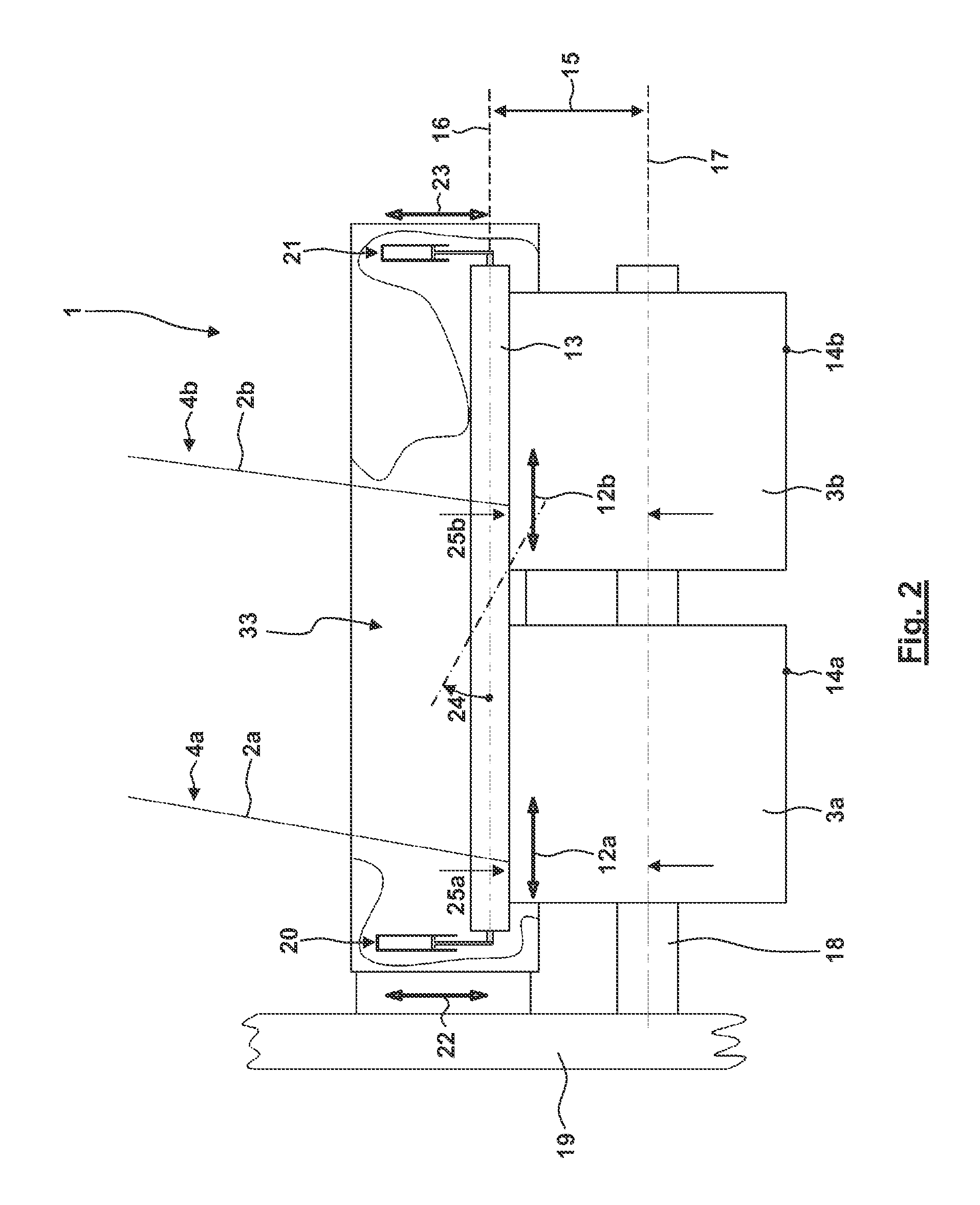
[0061]Referring now in greater detail to the drawings, FIG. 1 illustrates a winding machine 1. As can be seen in FIGS. 2 and 3 in more detail, in the winding machine 1 the parallel feeding of winding material 2a, 2b to the wound package 3a, 3b is carried out via feeding paths 4a, 4b. The feeding paths 4a, 4b are offset relative to each other in a direction vertical to the plane of projection of FIG. 1. In the description, corresponding elements in the feeding paths 4a, 4b are labelled with the same reference numerals with added letters a or b. respectively. The person with skill in the art will know that also more than the two shown parallel feeding paths 4a, 4b might be implemented in the winding machine 1.

[0062]In the following, the path of the winding material 2a, 2b via the feeding paths 4a, 4b is described for the winding material 2a via the feeding path 4a in the first line (wherein the corresponding applies for the winding material 2b in the parallel feeding path 4b):

[0063]Th...


PUM


Abstract

The invention relates to a winding machine. Winding material is continuously fed along feeding paths to two wound packages. A control signal is generated for actuating actuators. The actuators change the pressing force pressing a pressure roller at at least one wound package. The control signal depends on a tension of the winding material. In case that the tension of the winding material in a path to a wound package exceeds a predetermined tension the pressing force of the pressure roller at the associated wound package is increased. Accordingly the radius of the outer surface of the associated wound package is reduced. This reduction is intended for counteracting the undesired increase of the tension in the winding material.

Description

CROSS REFERENCE TO RELATED APPLICATIONS[0001]This application claims priority to co-pending German Patent Application No. DE 10 2011 052 699.4 entitled “Spulmaschine and Verfahren zur Steuerung derselben”, filed Aug. 12, 2011.FIELD OF THE INVENTION[0002]The present invention generally relates to a method for controlling a winding machine, wherein continuously supplied or fed winding material, especially a yarn, a thread, a tape, a ribbon, a wire, a twine etc. is simultaneously wound to two or multiple wound packages. During the winding process the packages are positioned and supported by a common spindle. Further, the invention relates to a winding machine. The winding machine simultaneously winds continuously fed winding material to multiple wound packages.BACKGROUND OF THE INVENTION[0003]In known winding machines, continuously fed winding material is fed from a supply station. The supply station is in particular built by the production device for the winding material or a stock un...

Claims


Application Information

Patent Timeline
Patent Type & Authority Applications(United States)
IPC IPC(8): B65H59/08
CPCB65H54/20B65H59/385B65H54/52B65H54/22B65H54/70B65H59/38B65H63/028B65H59/00B65H59/40B65H61/00G01L5/10
Inventor GORKE, CARSTEN
Owner GEORG SAHM GMBH & CO KG
Why Eureka
Try Eureka