Spark plug designed to increase service life thereof

Active Publication Date: 2013-02-14
DENSO CORP
View PDF3 Cites 2 Cited by
  • Summary
  • Abstract
  • Description
  • Claims
  • Application Information

AI Technical Summary

Benefits of technology

[0016]In the preferred mode of the invention, a distance L between the inward top end protrusion and the center electrode and a size G of the spark gap in the axial direction of the spark plug are so selected as to meet a relation of G<L. This avoids the creation of sparks between the inward top end protrusion and the center electrode, thus ensuring the stability in developing sparks in the spark gap to ignite fuel in the engine.
[0017]It is preferable that the distance L and the size G of the spark gap are so selected as to satisfy a relation of G+0.5 mm<L. This avoids the discharge of sparks to the inward top end protrusion when the spark gap is increased with time, thus ensuring the ignitability of the fuel in the engine.
[0018]The top of the center electrode may extend outside the top end of the cylindrical housing toward the top of the spark plug. This permits the inward top end protrusion to be increased in area thereof facing the periphery of the center electrode to promote the strength of an electric field s

Problems solved by technology

Specifically, the size of the spark gap is increased gradually by spark discharge events during the operation of the spark plug, which leads to an increase in voltage required to be developed between the center electrode and the ground electrode for producing the spark.
The decrease in initial spark gap, however, results in an increase in possibility that an initial flame of the air-fuel mixture is quenched, which leads to a failure in igniting the mixture.
This, however, results in an increase in overall production cost of the spark plug.
This, however, also results in an increase in overall production cost of the spark plug and in a deterioration of ignitability of the mixture in the engine.
It further causes a drop in

Method used


Image

  • Spark plug designed to increase service life thereof
  • Spark plug designed to increase service life thereof
  • Spark plug designed to increase service life thereof

Examples


Example

Test Example 1

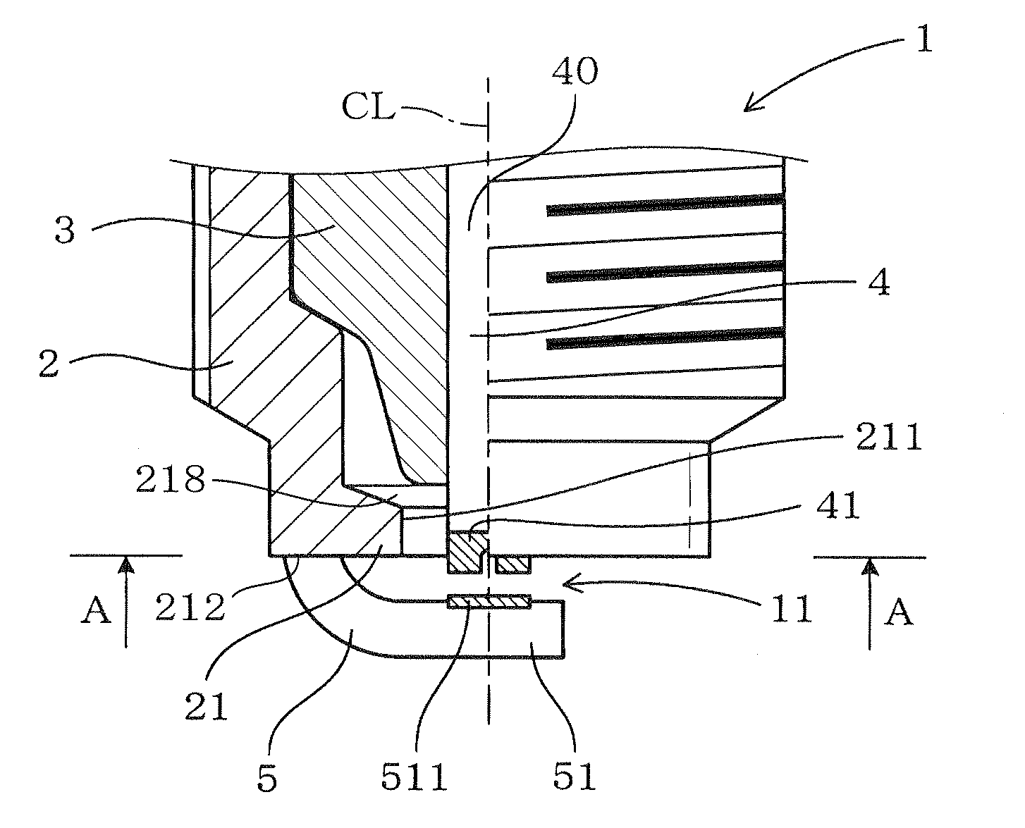
[0085]We performed tests on samples of the spark plug 1 of FIG. 1 and a comparative spark plug 9, as illustrated in FIG. 17, which does not have the inward top end protrusion 21 to evaluate a difference in required voltage between the spark plugs 1 and 9. In FIG. 17, the same reference numbers as employed in the first embodiment will refer to similar parts.

[0086]The samples of the spark plug 1 used in the tests each have the following dimensions. L=2 mm. t=1 mm. D=2 mm. H=0.5 mm. These characters are the same as those described in FIG. 5.

[0087]The samples of the spark plug 9 each have the structure, as illustrated in FIG. 17. The distance Lc between an inner edge of the top end of the metal shell 2 and the periphery of the center electrode 4 is 4 mm. Other dimensions are identical with those of the spark plug 1.

[0088]The samples of each of the spark plugs 1 and 9 have different sizes G of the spark gap 11 which range from 0.2 mm to 1.4 mm in increments of 0.2 mm.

[0089]...

Example

Test Example 2

[0092]We also performed tests, as illustrated in FIG. 18, to analyze effects of a relation between a minimum distance between the top corner 214, as illustrated in FIG. 5, of the inner top end 211 of the inward top end protrusion 21 and the top end corner 411 of the center electrode 4 and the distance L between the inner top end 211 of the inward top end protrusion 21 and the periphery of the center electrode 4 on the required voltage at the spark plug 1.

[0093]The minimum distance between the top corner 214 of the inner top end 211 of the inward top end protrusion 21 and the top end corner 411 of the center electrode 4 is expressed by (H2+L2)1 / 2 where H and L are the dimensions as already described in FIG. 5.

[0094]We prepared samples of the spark plug 1 which are different in value of (H2+L2)1 / 2 from each other. Each sample has the following dimensions: G=0.3 mm, t=1 mm, and D=2 mm. We performed the tests on the samples to measure the required voltages in the same way,...

Example

Test Example 3

[0096]We also performed tests, as illustrated in FIG. 19, to analyze effects of a relation between the thickness t of the inner top end 211, as defined in the axial direction of the spark plug 1, and the diameter D of the top end of the center electrode 4 (i.e., the noble metal chip 41) on the required voltage at the spark plug 1.

[0097]We prepared samples of the spark plug 1 which have the following dimensions: G=0.4 mm, L=2 mm, and H=1 mm. The samples also have different values of the diameter D which are 0.5 mm, 1.0 mm, 2.0 mm, and 3.0 mm and different values of the thickness t. The characters G, L, H, D, and t represent the same dimensions as described in FIG. 5.

[0098]We performed the tests on the samples to measure the required voltages in the same way, as described in TEST EXAMPLE 1. The results of the tests are shown in a graph of FIG. 19. Each line is defined by connecting the results of the tests on the samples whose diameter D is the same. The unit of D is mil...


PUM


Abstract

A spark plug for an internal combustion engine is provided which is equipped with an inward top end protrusion. The inward top end protrusion extends inwardly from a top end of a cylindrical housing within which a porcelain insulator is disposed. The porcelain insulator has a center electrode disposed therein. The inward top end protrusion is at least partially located to be closer to the top of the spark plug than a top end of the porcelain insulator is in an axial direction of the spark plug. This enhances the strength of an electric field surrounding the center electrode, which facilitates the ease with which an electron is emitted by the center electrode and thus permits an initial required voltage at the spark plug to be decreased, thereby resulting in an increase in service life of the spark plug.

Description

CROSS REFERENCE TO RELATED DOCUMENT[0001]The present application claims the benefit of priority of Japanese Patent Application Nos. 2011-173090 filed on Aug. 8, 2011 and 2012-87382 filed on Apr. 6, 2012, the disclosures of which are incorporated herein by reference.BACKGROUND OF THE INVENTION[0002]1. Technical Field[0003]This disclosure relates generally to an improved structure of a spark plug which may be used in internal combustion engines for automotive vehicles and is designed to increase the service life thereof.[0004]2. Background Art[0005]Japanese Patent First Publication No. 11-219771 discloses a spark plug equipped with a center electrode and a ground electrode which defines a spark gap therebetween to produce a sequence of sparks to ignite an air-fuel mixture admitted into a combustion chamber of an internal combustion engine.[0006]The service life of such a type of spark plug usually depends upon a rise in required voltage resulting from an increase in size of the spark ...

Claims


Application Information

Patent Timeline
IPC IPC(8): H01T13/00
CPCH01T13/20H01T13/50H01T13/32
Inventor YAMANAKA, KOUJI
Owner DENSO CORP
Why Eureka
Try Eureka