
Apparatus and method for adaptive beam-forming in wireless communication system

Active Publication Date: 2013-02-14
SAMSUNG ELECTRONICS CO LTD
View PDF5 Cites 193 Cited by
  • Summary
  • Abstract
  • Description
  • Claims
  • Application Information

AI Technical Summary

Benefits of technology

The present invention provides an apparatus and method for effective beam-forming in a wireless communication system. This technology addresses the problems and disadvantages of previous methods and provides improved performance.

Problems solved by technology

However, it has become difficult to meet the continually increasing RF data traffic demands with only improvements in the spectral efficiency.
The reason for this is that it is very difficult to secure a wider frequency band at 10 GHz or less.
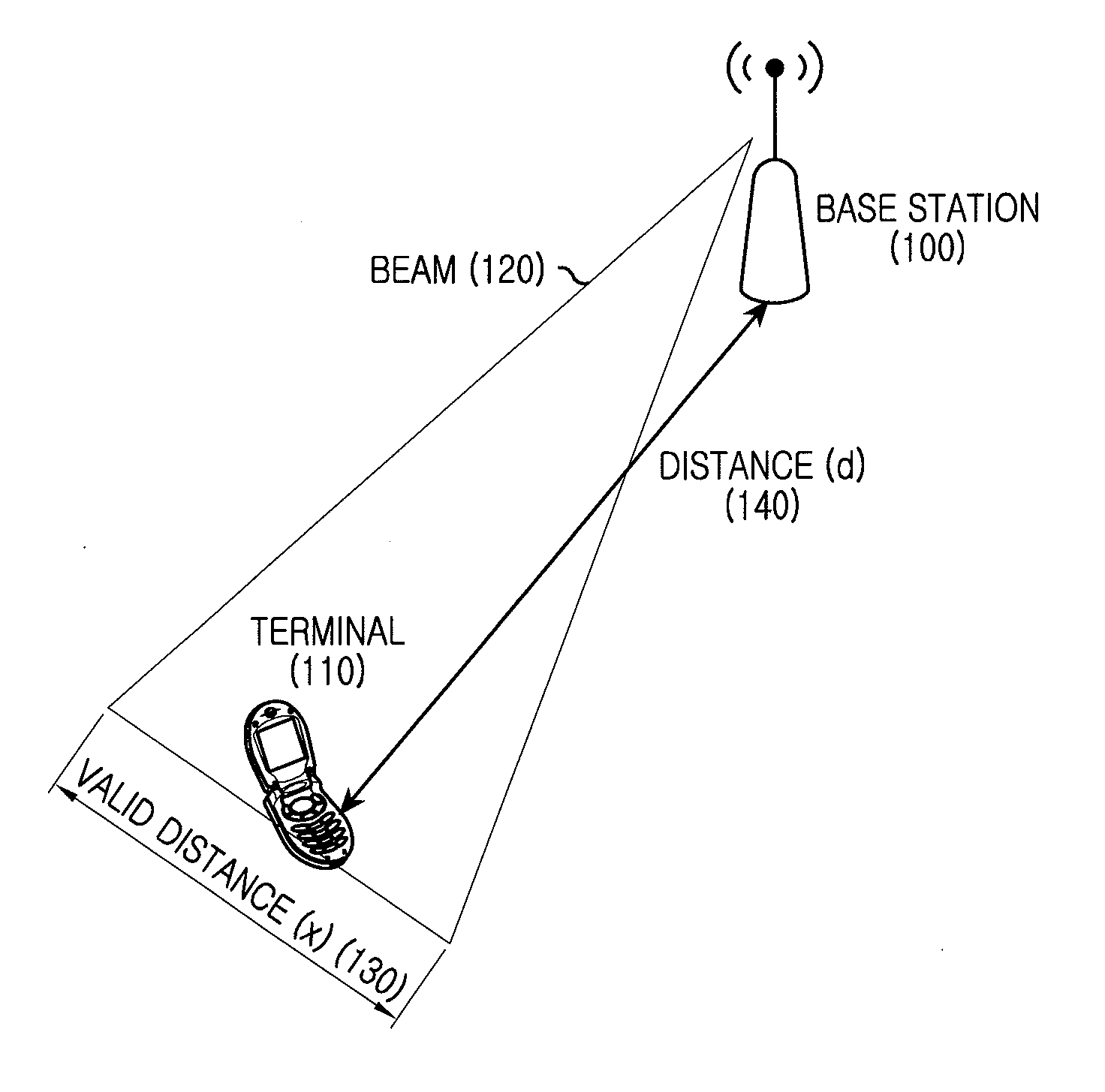
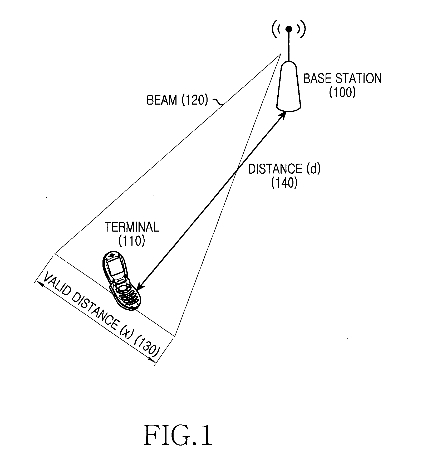
However, the use of the super high frequency band has a shortcoming in that as a frequency for wireless communication increases, a radio path loss increases.
Accordingly, as the frequency for wireless communication increases, radio reach distance is correspondingly shortened, thereby resulting in a reduced service coverage area.

Method used


Image

  • Apparatus and method for adaptive beam-forming in wireless communication system
  • Apparatus and method for adaptive beam-forming in wireless communication system
  • Apparatus and method for adaptive beam-forming in wireless communication system

Examples


Embodiment Construction

[0031]The following description with reference to the accompanying drawings is provided to assist in a comprehensive understanding of exemplary embodiments of the invention as defined by the claims and their equivalents. It includes various specific details to assist in that understanding but these are to be regarded as merely exemplary. Accordingly, those of ordinary skill in the art will recognize that various changes and modifications of the embodiments described herein can be made without departing from the scope and spirit of the invention. Also, descriptions of well-known functions and constructions are omitted for clarity and conciseness.

[0032]The terms and words used in the following description and claims are not limited to the bibliographical meanings, but, are merely used by the inventor to enable a clear and consistent understanding of the invention. Accordingly, it should be apparent to those skilled in the art that the following description of exemplary embodiments of ...


PUM


Abstract

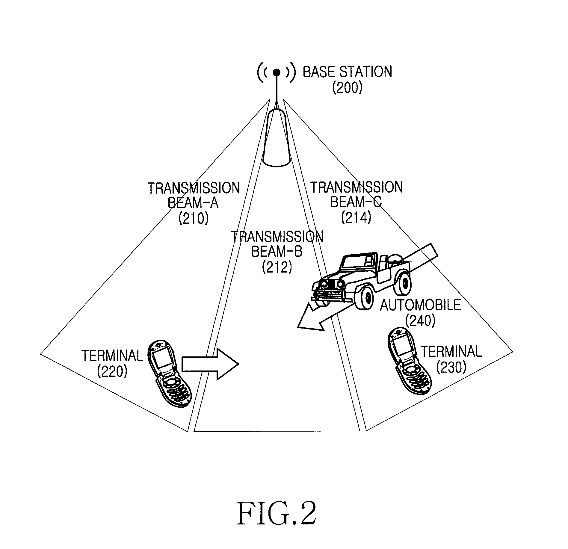
Apparatuses and methods for maintaining an optimal beam direction in a wireless communication system are provided. The method for operating a receiving node in a wireless communication system includes, determining a first transmission beam is determined as a preferred transmission beam using a plurality of reference signals transmitted by a transmitting node, generating preferred transmission beam information, transmitting the preferred transmission beam information to the transmitting node, receiving transmissions from the transmitting node via the first transmission beam, and determining whether a change of a transmission beam is necessary. When the change of the transmission beam is determined to be necessary, generating a beam change request and transmitting the beam change request to the transmitting node.

Description

PRIORITY[0001]This application claims the benefit under 35 U.S.C. §119(a) of a Korean patent application filed in the Korean Intellectual Property Office on Aug. 12, 2011 and assigned Serial No. 10-2011-0080676, the entire disclosure of which is hereby incorporated by reference.BACKGROUND OF THE INVENTION[0002]1. Field of the Invention[0003]The present invention relates to a wireless communication system. More particularly, the present invention relates to an apparatus and a method for adaptively performing beam forming in a wireless communication system that uses a Super High Frequency (SHF) band.[0004]2. Description of the Related Art[0005]To meet continually increasing Radio Frequency (RF) data traffic demands, wireless communication systems are evolving so as to support higher data transmission rates. For example, an emphasis in the development of a 4th Generation (4G) wireless communication system is an improvement in spectral efficiency in order to increase a data transmission...

Claims


Application Information

Patent Timeline
IPC IPC(8): H04W72/08
CPCH04W72/046H04B7/0408H04L1/1867H04B7/0617H04B7/0619H04B7/0695H04B7/086H04L1/1812H04W72/21H04W72/23H04W84/042
Inventor KIM, TAE-YOUNGYU, HYUN-KYUCHO, JAE-WEON
Owner SAMSUNG ELECTRONICS CO LTD
Learn More