
Hybrid structure airfoil

a hybrid structure and airfoil technology, applied in the field of hybrid structure airfoils, can solve the problems of increasing the cost of the fan blades

Active Publication Date: 2013-02-14
RAYTHEON TECH CORP
View PDF2 Cites 81 Cited by
  • Summary
  • Abstract
  • Description
  • Claims
  • Application Information

AI Technical Summary

Benefits of technology

The present invention provides a hybrid fan blade for a gas turbine engine that includes a body and a composite panel. The composite panel is attached to the body and sized to enclose an opening. The fan blade has a load bearing structure that is operable to transfer loads to the body and receive loads from the body. This invention allows for the efficient transfer of loads between the body and the composite panel, which can improve the fatigue resistance and durability of the fan blade.

Problems solved by technology

Both the first and the second approaches typically result in a weight reduction over a traditional titanium solid fan blade, but dramatically increase the cost of the fan blade.

Method used


Image

  • Hybrid structure airfoil
  • Hybrid structure airfoil
  • Hybrid structure airfoil

Examples


Embodiment Construction

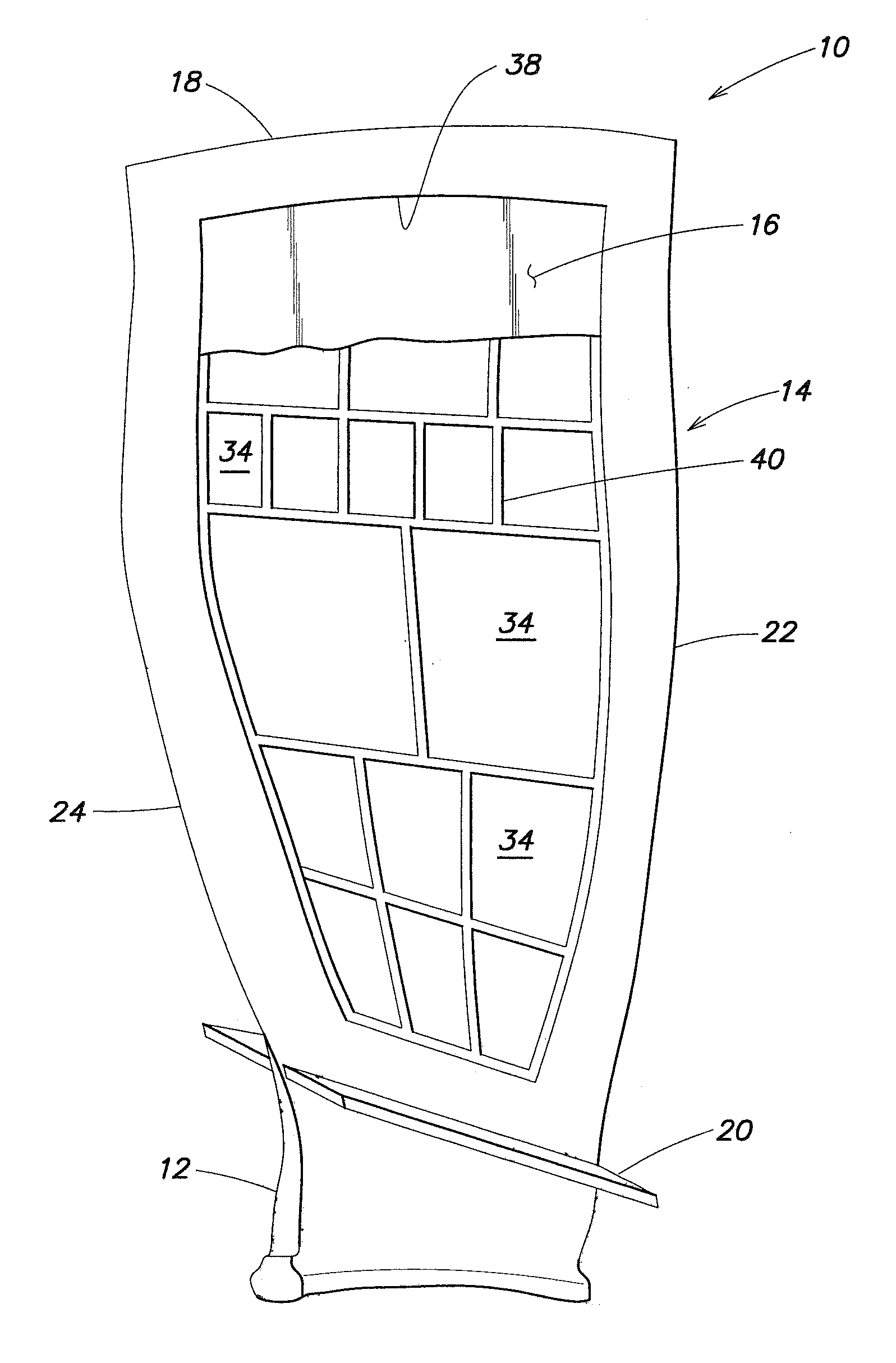
[0017]Now referring to FIG. 1, a hybrid airfoil 10 (e.g., a fan blade, a compressor blade, a rotor blade, etc.) for a gas turbine engine is provided that includes a base 12, a body 14, and a composite panel 16 disposed in, and forming a part of, a side of the body 14. The base 12 includes means for attaching the airfoil 10 to a rotor hub (not shown) disposed in the engine.

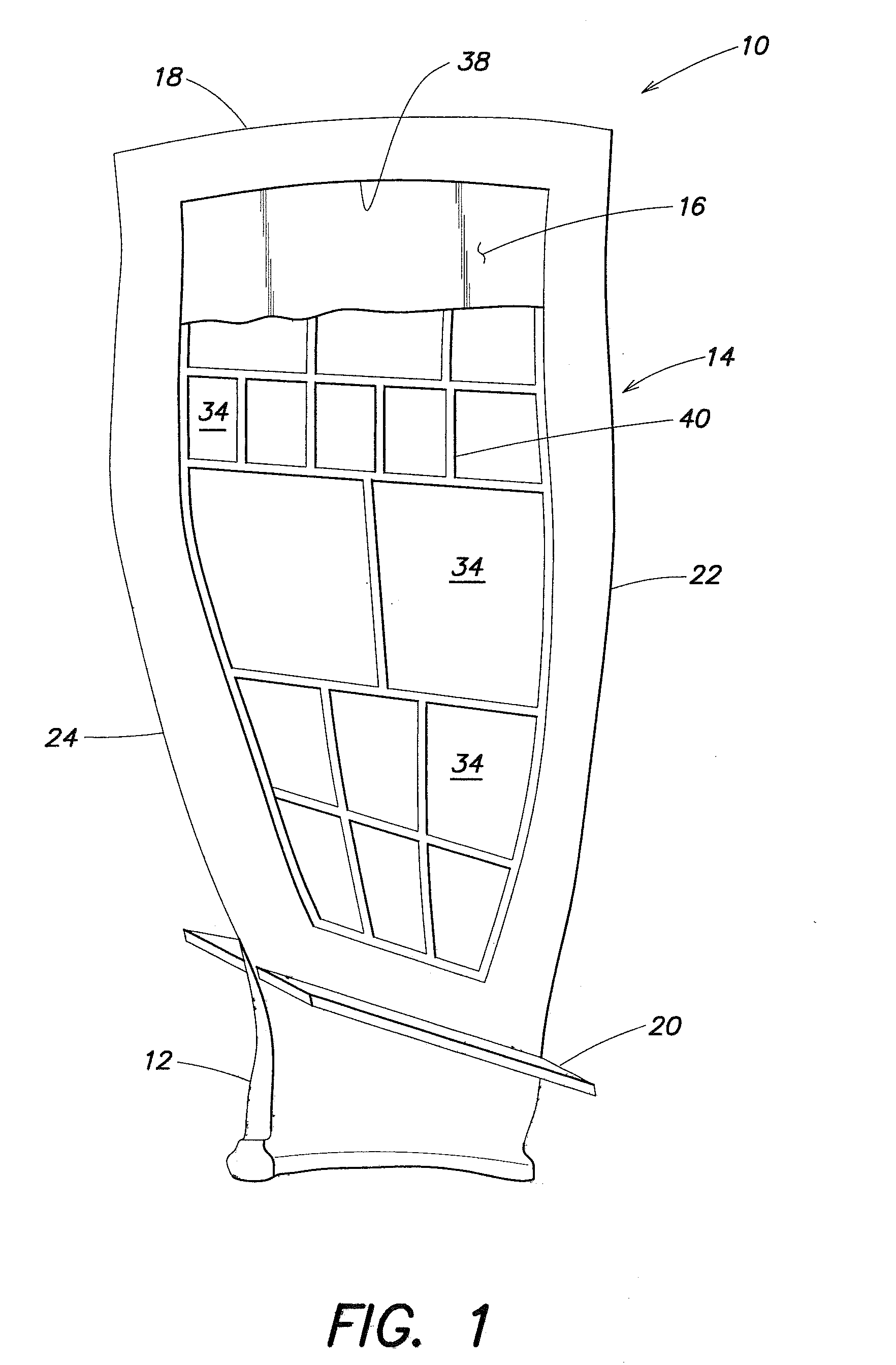
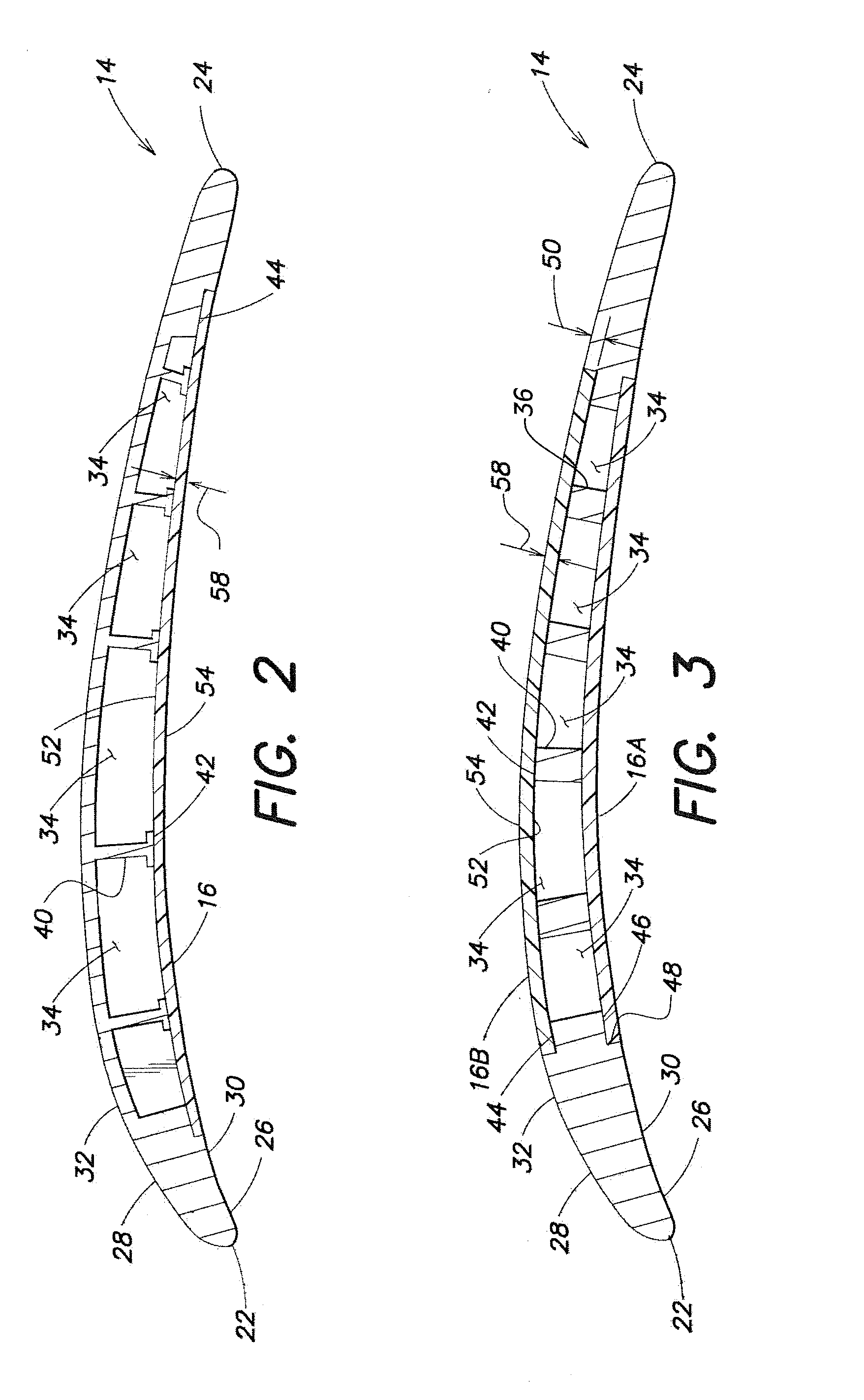
[0018]The body 14 includes a tip 18, a base 20, a leading edge 22, a trailing edge 24, a first side 26 and a second side 28. The second side 28 is orientated opposite the first side 26. The first and the second sides 26, 28 extend between the tip 18, the base 20, the leading edge 22, and the trailing edge 24. The first side 26 of the body 14 has a first outer surface 30, and the second side 28 has a second outer surface 32.

[0019]At least one side 26, 28 of the body 14 includes a plurality of cavities 34, extending inwardly toward the opposite side 28, 26. In the embodiment shown in FIGS. 1 and 2, the cavities 34 ar...


PUM

PropertyMeasurementUnit
Metallic bondaaaaaaaaaa

Abstract

A hybrid airfoil for a gas turbine engine is provided that includes a body and a panel. The body has a first side and a second side orientated opposite the first side. The first and second sides extend between a tip, a base, a leading edge and a trailing edge. The body includes a plurality of cavities disposed in the first side of the body, which cavities extend inwardly toward the second side. The cavities collectively form an opening. At least one rib is disposed between the cavities. A shelf is disposed around the opening. The panel is attached to the shelf first mounting surface and to the rib, and is sized to enclose the opening. The panel is a load bearing structure operable to transfer loads to the body and receive loads from the body.

Description

CROSS-REFERENCE TO RELATED APPLICATIONS[0001]This application is a continuation-in-part of U.S. patent application Ser. No. 12 / 425,133, which is hereby incorporated by reference in its entirety.BACKGROUND OF THE INVENTION[0002]1. Technical Field[0003]This disclosure relates to gas turbine engine airfoils in general, and to a hybrid airfoil utilizing composite and / or metallic materials in particular.[0004]2. Background Information[0005]Lightweight fan blades such as hybrid fan blades have been developed to reduce weight, centrifugal forces and inertial stress and strain in gas turbine engines. Some fan blades include a unitary hollow metallic airfoil portion formed by casting, forging and other forming techniques followed by milling to final dimensions. Other fan blades include metallic leading edge, trailing edge, and tip portion, independent of one another, fixed to a composite body. The metallic leading and trailing edges are bonded to the composite airfoil to provide erosion and ...

Claims


Application Information

Patent Timeline
IPC IPC(8): F01D5/12F01D5/28F01D5/14F01D5/18
CPCF01D5/147F01D5/16F01D5/282F04D29/023F04D29/324Y02T50/673F05D2260/96F05D2300/603F05D2300/612F05D2300/615Y02T50/672F04D29/388Y02T50/60
Inventor VIENS, DANIEL V.NARDONE, VINCENT C.SMITH, PETER G.STRIFE, JAMES R.LAMM, FOSTER P.
Owner RAYTHEON TECH CORP
Features
  • Generate Ideas
  • Intellectual Property
  • Life Sciences
  • Materials
  • Tech Scout
  • Unparalleled Data Quality
  • Higher Quality Content
  • 60% Fewer Hallucinations
Learn More