Wetness sensors

a sensor and wet body technology, applied in the field of wet body sensors, can solve the problems of substantial inoperative operation of the rf circui

Active Publication Date: 2013-02-14
3M INNOVATIVE PROPERTIES CO
View PDF8 Cites 149 Cited by
  • Summary
  • Abstract
  • Description
  • Claims
  • Application Information

AI Technical Summary

Benefits of technology

[0010]Absorbent garments such as diapers, as well as other articles, that incorporate the disclosed wetness sensors are also disclosed. In the case of an absorbent garment, the garment may include a liquid-permeable sheet, a liquid-impermeable sheet, and an absorbent material trapped between the liquid-permeable sheet and the liquid-impermeable sheet. The wetness sensor may be disposed between the liquid-permeable sheet and the liquid-impermeable sheet, or between the liquid-permeable sheet and a user's body. Preferably, the wetness sensor is disposed between the liquid-impermeable sheet and the absorbent core so that it will degrade when the core is saturated and will not be triggered by the release of only a small amount of target fluid.

Problems solved by technology

The contact by the target fluid may substantially render the RF circuit inoperative.

Method used


Image

  • Wetness sensors
  • Wetness sensors
  • Wetness sensors

Examples


example 1

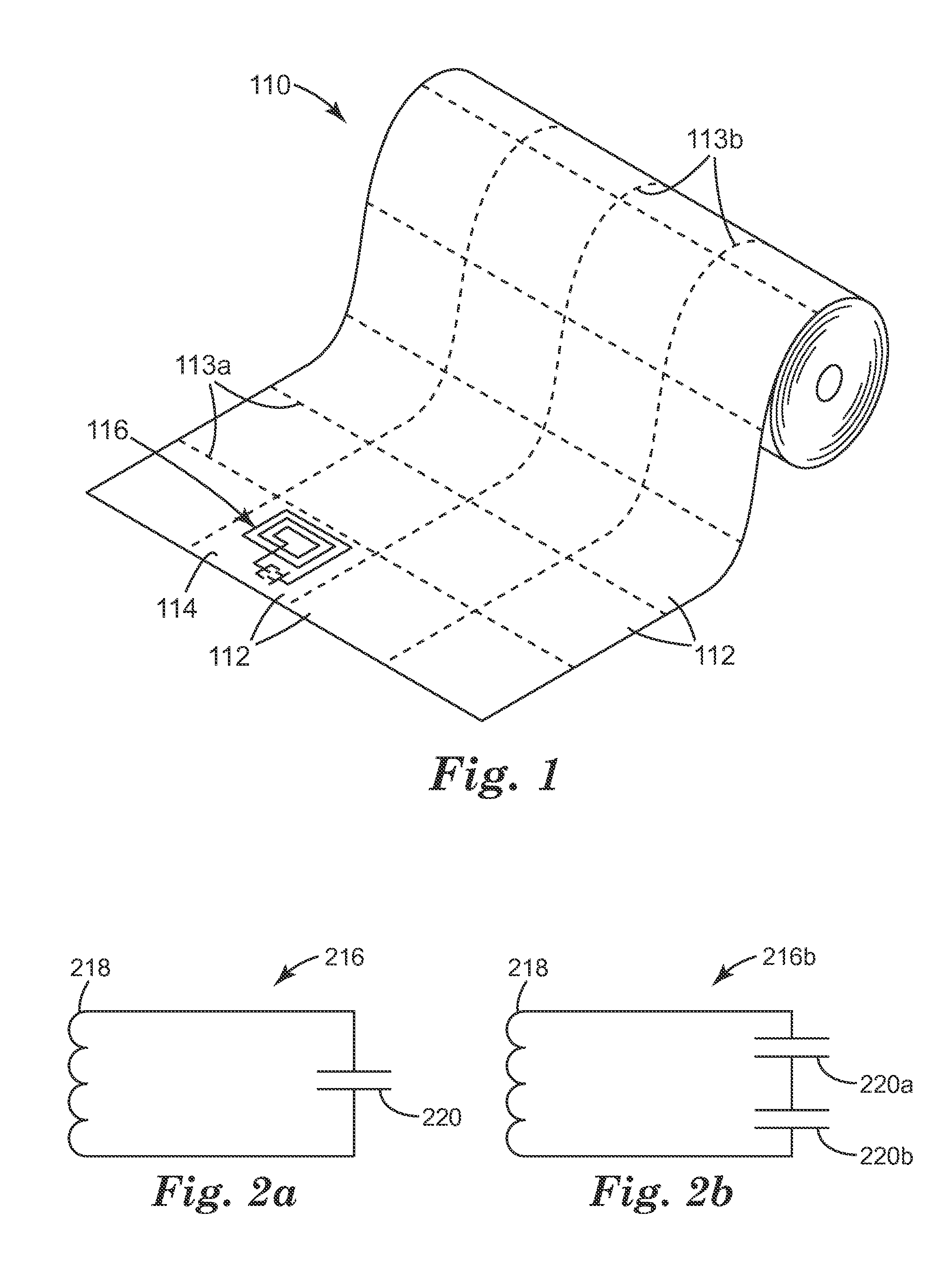
[0095]A sheet of polyvinyl alcohol (PVA) film (available as “Monosol M8630” from Monosol, LLC, Portage, Ind., USA) having a measured thickness of two mils (about 51 micrometers) was used as the self-supporting substrate. The sheet of PVA film was held down on a silk screening table using vacuum. Placed against this sheet was a 157 mesh silk screen, the silk screen having imaged therein an array of patterns corresponding to the printed circuit elements 1116 of FIG. 11. The particular pattern of the example was an inductive coil having about six turns arranged in a spiral. The conductive ink was then pattern-wise applied to the PVA sheet through the silk screen by applying even pressure to a squeegee. The silk screen was then removed, yielding the printed sheet 1110 as generally depicted in FIG. 11. The printed sheet was allowed to air dry overnight on a drying rack. The procedure was repeated for the application of a total of three different conductive inks (CI-2001, CI-5001, CI-1001...

examples 2-10

[0100]Examples 2 through 10 describe the fabrication of strip-shaped and U-shaped samples having a layer of conductive material completely covering one major surface or side of the respective strip-shaped or U-shaped substrate. Such samples may be used, for example, as jumpers in the disclosed tuned RF circuits. However, the reader will understand that the design of such samples can be readily modified, e.g. by suitably patterning the electrically conductive material to provide tags having one or more inductive coil(s) and / or other circuit element(s) carried by a substrate, such a tag representing or providing at least a portion of a tuned RF circuit. Such a tag would have analogous electrical properties (before and after wetting) as those reported below for the samples of Examples 2-10.

example 2

[0101]Individual sheets of polyvinyl alcohol (PVA) film (available as “Monosol M8630” from Monosol, LLC, Portage, Ind., USA) having measured thicknesses of 2, 4, and 6 mils (about 51, 102, and 153 micrometers respectively) were used as self-supporting substrates. Silver films were coated onto 127 mm by 178 mm samples of the PVA film substrates by magnetron physical vapor deposition. The silver films were sputter deposited from a silver metal target. The PVA substrates were placed on a substrate holder set up inside a vacuum chamber with a sputtering silver target located at a height of 178 mm above the substrate holder. After the chamber was evacuated to 1×10⁻⁵ torr base pressure, sputter gas argon was admitted inside the chamber at a flow rate of 50 sccm (standard cubic centimeter per minute) using a mass flow controller. The total pressure of the chamber was adjusted to 2 milliTorr. Sputtering was initiated using a DC power supply at a constant power level of 0.10 kilowatts. The s...


PUM


Abstract

A wetness sensor includes a self-supporting substrate and an electrically conductive trace carried by the substrate. The trace is patterned to provide at least a portion of a tuned RF circuit, which may be disposed on only one side of the substrate and characterized by an impedance or resistance. The trace is not self-supporting. The substrate is adapted to dissolve, swell, or otherwise degrade when contacted by a target fluid. Such degradation produces a drastic change in the operation of the RF circuit, which can be interpreted by a remote reader as a “wet” condition. Contact of the substrate by the target fluid may change the impedance or resistance of the RF circuit by at least a factor of 5, 10, 100, or 1000, and / or may cause the trace to disintegrate so as to provide the RF circuit with an open circuit, and / or may substantially render the RF circuit inoperative.

Description

FIELD OF THE INVENTION[0001]This invention relates generally to wetness sensors, as well as articles and systems that incorporate such sensors, and methods pertaining to such sensors.BACKGROUND[0002]Millions of young and old wear diapers every day. For both of these groups, checking for wetness may require relying on others. In the case of adult patients who are wearing a diaper due to a medical condition or life situation, an unnoticed wet diaper can become a health risk to the occupant in some circumstances. Diaper rash and skin ulcers are just two possible medical conditions that may result from prolonged exposure to wetness. For both the health risk to the patient and the possible monetary liability for the health care provider, processes and procedures for enhanced diaper monitoring are desirable.[0003]In some places, standard monitoring procedures for adult patients requiring the use of a diaper is to monitor the patient for incontinence at least once every four hours. If the ...

Claims


Application Information

Patent Timeline
Patent Type & Authority Applications(United States)
IPC IPC(8): A61F13/42G01R27/08
CPCA61F13/42
Inventor PRIOLEAU, LORI-ANN S.JOHNSON, JUSTIN M.LORENTZ, ROBERT D.BADRI, BRINDA B.VANOUS, JAMES C.CHATTERTON, JACOB D.PERRON, STEVEN J.BATTLES, DONALD R.VEERARAGHAVAN, BADRI
Owner 3M INNOVATIVE PROPERTIES CO
Why Eureka
Try Eureka