
Heat front capture in thermal recovery simulations of hydrocarbon reservoirs

a hydrocarbon reservoir and thermal recovery technology, applied in the direction of analogue processes, instruments, borehole/well accessories, etc., can solve the problems of monotonic dg method and local conservative energy, and achieve the effect of improving the stability of analysis

Active Publication Date: 2013-02-14
CONOCOPHILLIPS CO
View PDF3 Cites 25 Cited by
  • Summary
  • Abstract
  • Description
  • Claims
  • Application Information

AI Technical Summary

Benefits of technology

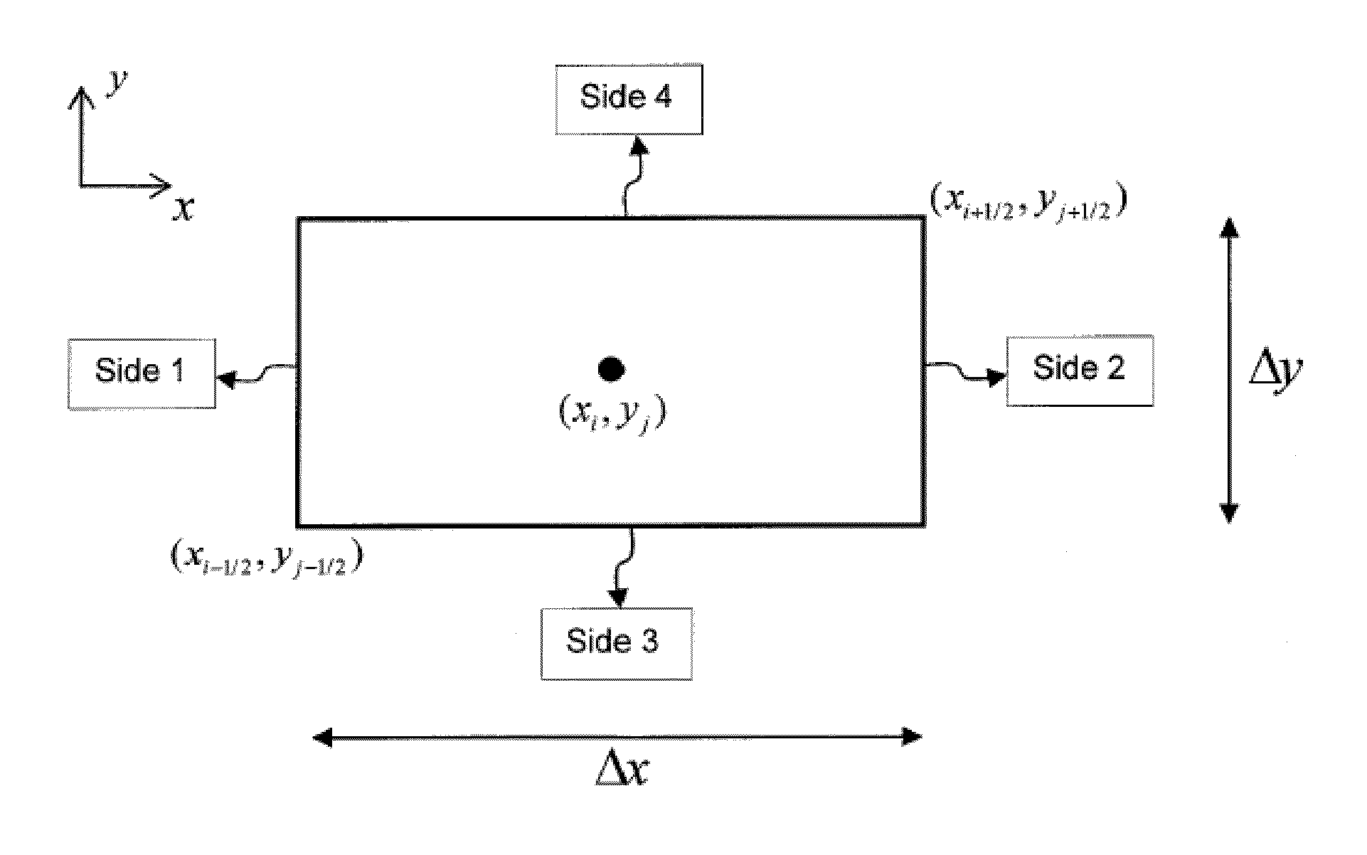
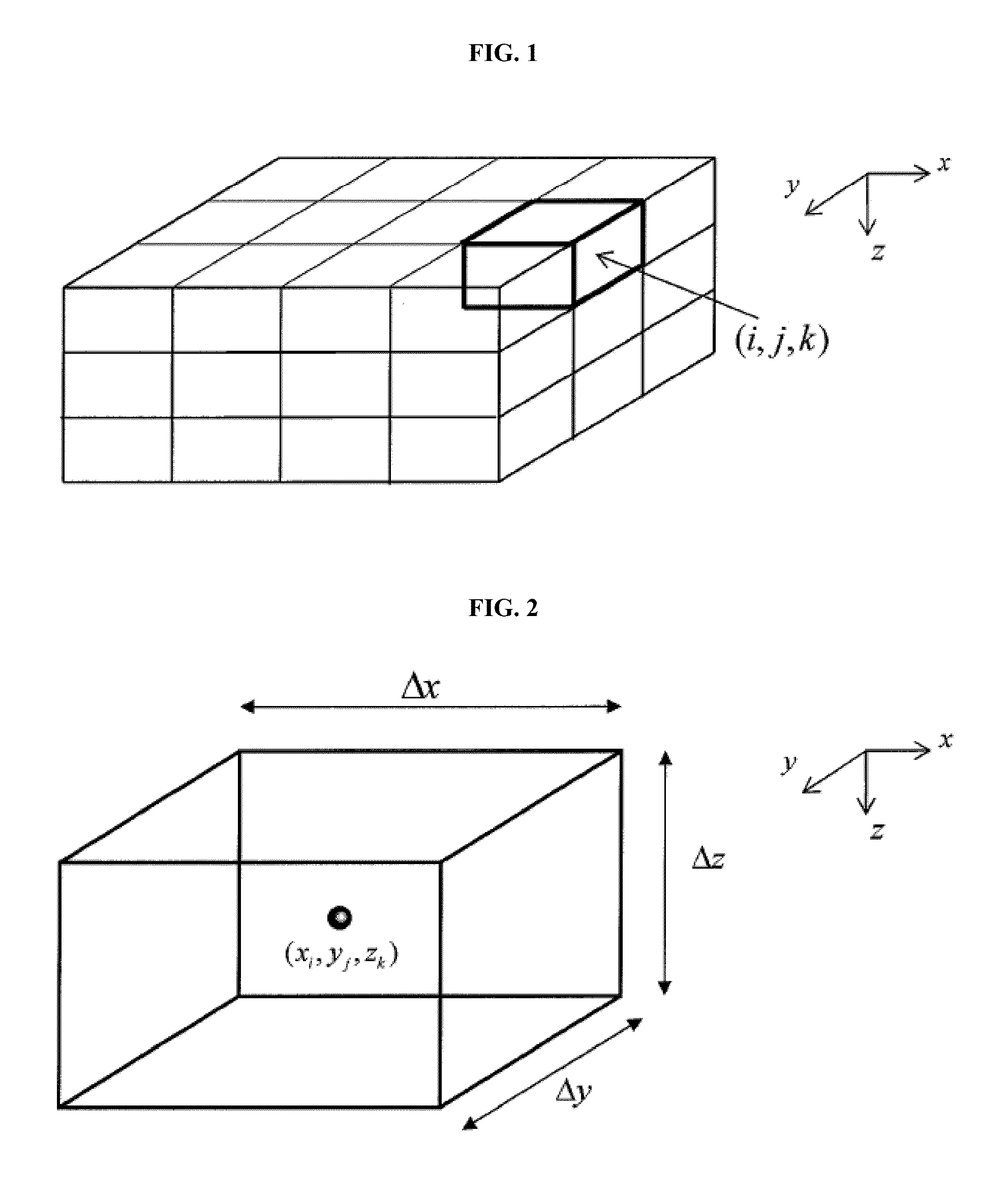
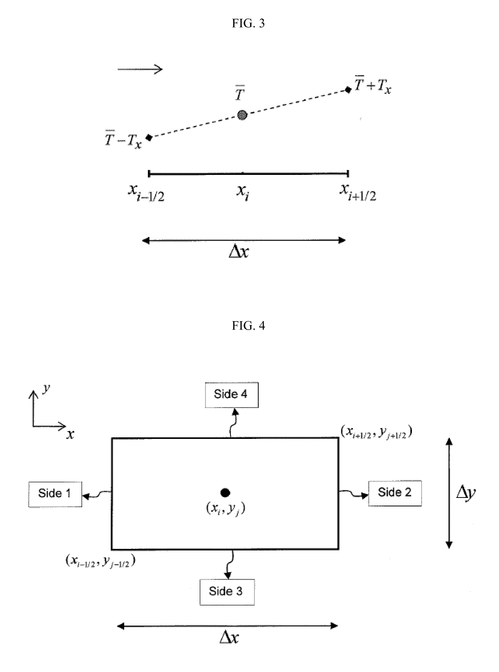
The present invention is about a new procedure for simulating thermal recovery processes in heavy oil reservoirs. It combines two existing methods: the FD method and the DG method. The FD method is used to approximate the pressure, saturations, and compositions, while the DG method is used to approximate the temperature and enthalpies. The new approach uses the DG method to solve both the flow and energy equations, resulting in improved accuracy of temperature at the grid-block interfaces and reduced numerical dispersion. The DG method can be used on both fm and coarse grids and is more efficient in reducing the number of grid-blocks required for a similar accuracy. The dynamic reservoir simulation involves partitioning the reservoir geometry into grid-blocks, assigning fluid and rock properties to the grid-blocks, calculating the average temperature at the center of the grid blocks and the temperatures at the grid blocks interfaces, using a slope limiter to improve stability, and solving the pressure, material balance, and energy balance equations.

Problems solved by technology

The DG method is monotonic and locally conservative of energy at the grid-block level.

Method used


Image

  • Heat front capture in thermal recovery simulations of hydrocarbon reservoirs
  • Heat front capture in thermal recovery simulations of hydrocarbon reservoirs
  • Heat front capture in thermal recovery simulations of hydrocarbon reservoirs

Examples


Embodiment Construction

[0030]Turning now to the detailed description of the preferred arrangement or arrangements of the present invention, it should be understood that the inventive features and concepts may be manifested in other arrangements and that the scope of the invention is not limited to the embodiments described or illustrated. The scope of the invention is intended only to be limited by the scope of the claims that follow.

[0031]In simulating hot fluid injection in heavy oil reservoir, the accuracy of the temperature solution is crucial. The FD method that is used in most of the thermal simulators has an inherent limitation. The FD method may produce significant numerical dispersion that results in smearing sharp fronts of temperature and therefore degrades the accuracy of the solution. A common practice to restore the accuracy is to refine the grid by increasing the number of grid-blocks. Since the FD method is a first order approximation scheme, the improvement in accuracy as a response to re...


PUM


Abstract

A numerical procedure is disclosed to improve the prediction of heat fronts when simulating hot fluid injection in viscous hydrocarbon reservoirs. The mathematical model is composed of the conventional governing equations that describe multiphase fluid flow and energy balance. The reservoir geometry can be partitioned into a regular Cartesian grid or an irregular corner-point geometry grid. The numerical procedure uses the finite different (FD) method to solve the flow equations and the discontinuous Galerkin (DG) method to solve the energy balance equation. The proposed FD-DG method is an alternative to the traditional solution procedure that uses the FD method to solve both the flow and the energy equations. The traditional method has the deficiency that it may require excessive number of grid cells to achieve acceptable resolution of the heat fronts. The proposed FD-DG method significantly reduces numerical dispersion near discontinuities in the solution of the energy equation and therefore provides a better capture of the heat fronts. To obtain a desired accuracy in the energy equation solution, the FD-DG method can be orders of magnitude faster than the traditional method. The superiority of the FD-DG method is that it converges on coarser grids while the traditional method requires much finer grids.

Description

CROSS REFERENCE TO RELATED APPLICATIONS[0001]None.STATEMENT OF FEDERALLY SPONSORED RESEARCH[0002]None.FIELD OF THE DISCLOSURE[0003]The present invention relates generally to a method for simulating oil recovery processes in hydrocarbon reservoirs. In one embodiment, a numerical model to simulate hot fluid injection in viscous and heavy oil reservoirs.BACKGROUND OF THE DISCLOSURE[0004]Viscous and heavy oil subsurface deposits represent a significant portion of the recoverable hydrocarbon reserve in the world. Heavy hydrocarbons cannot be efficiently recovered by the conventional oil recovery techniques (primary and secondary) because of relatively high viscosity and therefore low mobility of oil. Hot fluid injection is one of the successful techniques that is currently adopted in the industry to reduce oil viscosity and mobilize oil towards the production wells. Numerical methods are widely used in the oil industry as a means to model the mechanisms that dominate fluid flow behavior ...

Claims


Application Information

Patent Timeline
IPC IPC(8): G06F17/11G06G7/48
CPCE21B43/00
Inventor HOTEIT, HUSSEIN ALI
Owner CONOCOPHILLIPS CO
Learn More