
Physical quantity sensor and electronic apparatus

a technology of physical quantity and electronic equipment, applied in the direction of measuring devices, speed/acceleration/shock measurement, instruments, etc., can solve problems such as stage stuck

Active Publication Date: 2013-02-21
SEIKO EPSON CORP
View PDF12 Cites 35 Cited by
  • Summary
  • Abstract
  • Description
  • Claims
  • Application Information

AI Technical Summary

Benefits of technology

The patent text describes a physical quantity sensor that has improved performance in detecting acceleration. The sensor part has a through hole and a recess part, which reduces the flow resistance of a gas between the sensor part and the surface of the recess part. This allows for smoother displacement of the sensor part and faster response times. The sensor part is also balanced to efficiently rotate in response to acceleration. The sensor is made using insulating material, which facilitates insulation and isolation between the base substrate and the sensor part. Overall, the patent text describes a physical quantity sensor with improved performance and efficiency in detecting acceleration.

Problems solved by technology

Further, in the acceleration sensor, the swing stage may be stuck to the surface of the first semiconductor wafer due to charging caused by static electricity.

Method used


Image

  • Physical quantity sensor and electronic apparatus
  • Physical quantity sensor and electronic apparatus
  • Physical quantity sensor and electronic apparatus

Examples


first embodiment

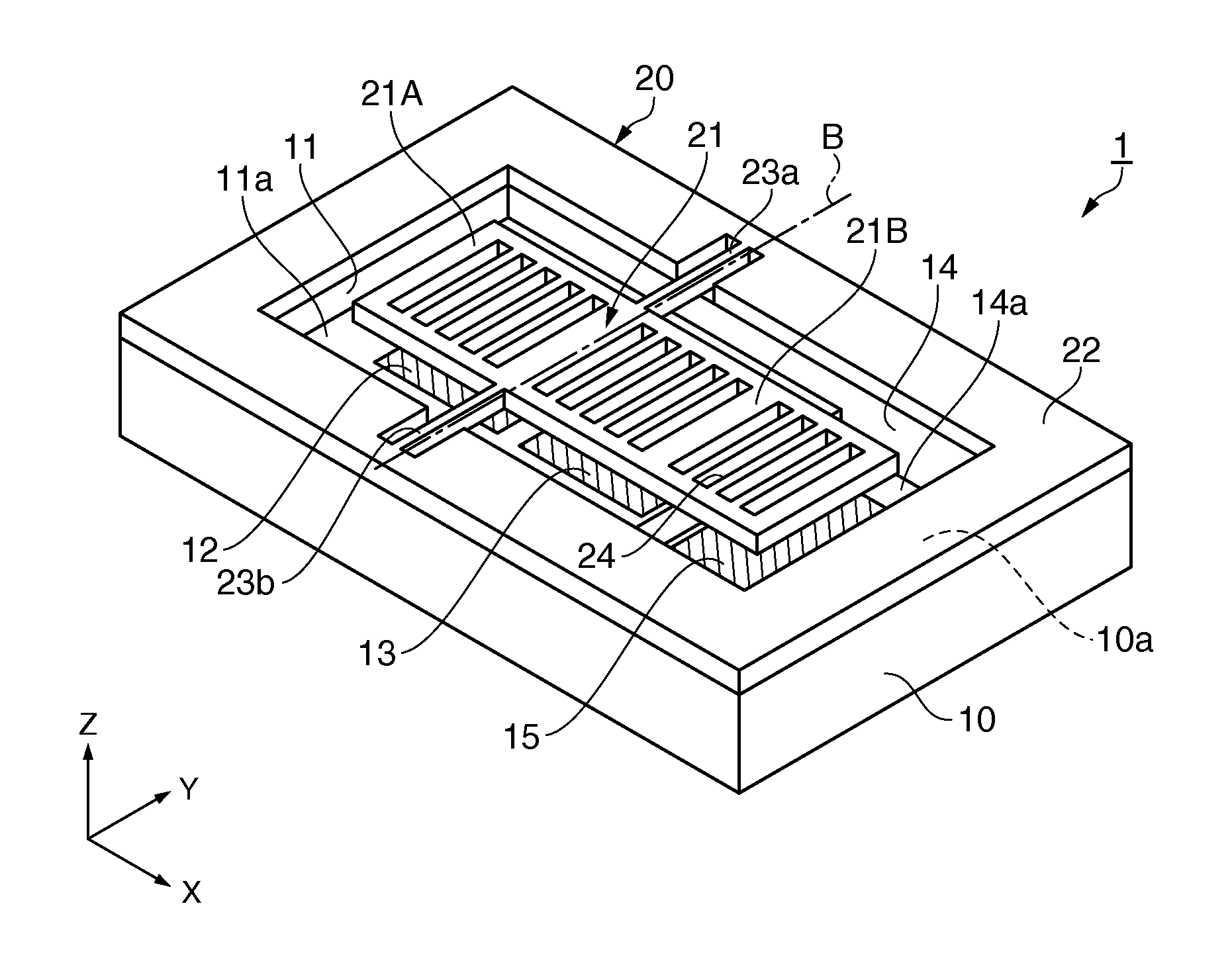
[0043]First, an acceleration sensor as an example of a physical quantity sensor according to a first embodiment will be explained. The acceleration sensor may detect acceleration in a Z-axis direction (thickness direction).

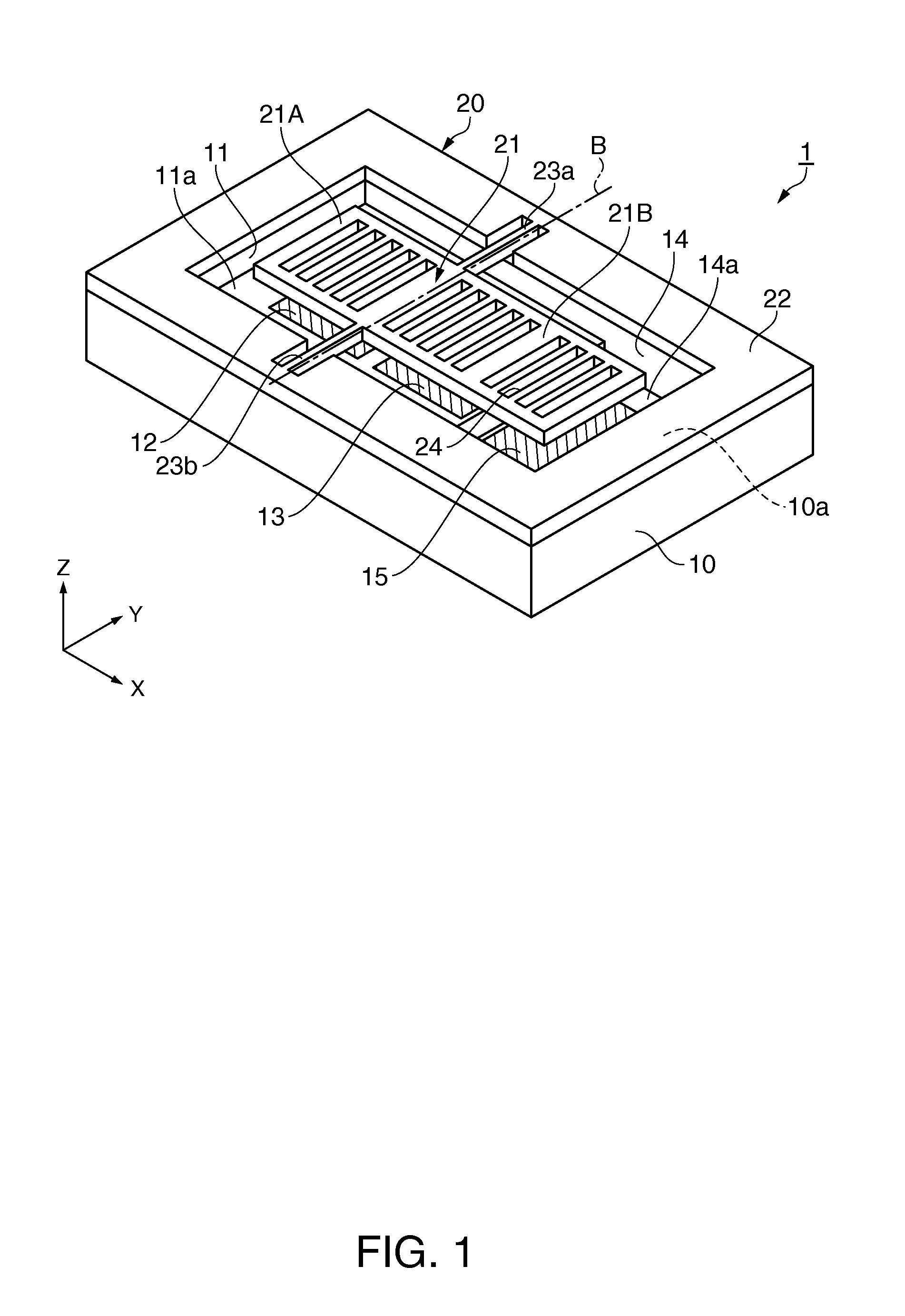
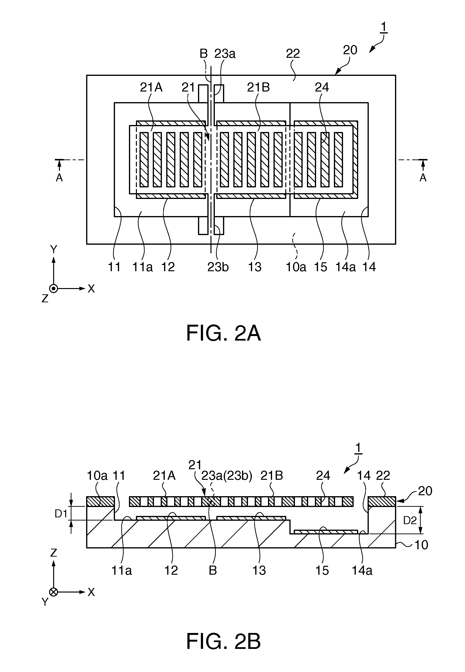
[0044]FIG. 1 is a schematic perspective view showing a general configuration of the acceleration sensor of the first embodiment. FIGS. 2A and 2B are schematic plan and sectional views of the acceleration sensor in FIG. 1, and FIG. 2A is a plan view and FIG. 2B is a sectional view along an A-A line in FIG. 2A.

[0045]As shown in FIGS. 1, 2A, and 2B, an acceleration sensor 1 includes a base substrate 10 and a sensor substrate 20.

[0046]The base substrate 10 has a nearly rectangular planar shape, and a first recess part 11 having a nearly rectangular planar shape is provided in a center part. It is preferable that an insulating material such as glass is used for the base substrate 10. For example, for the base substrate 10, glass containing alkali metal ions (movable io...

second embodiment

[0098]Next, an acceleration sensor according to a second embodiment will be explained. In the acceleration sensor of the second embodiment, the above described first recess part of the acceleration sensor of the first embodiment is formed in a step-like shape.

[0099]FIGS. 5A and 5B are schematic plan and sectional views showing a general configuration of the acceleration sensor of the second embodiment, and FIG. 5A is a plan view and FIG. 5B is a sectional view along an A-A line in FIG. 5A. Note that the parts in common with the first embodiment have the same signs and their detailed explanation will be omitted and the parts different from the first embodiment will be centered for explanation.

[0100]As shown in FIGS. 5A and 5B, in an acceleration sensor 2, a first recess part 111 of the base substrate 10 is formed in a step-like shape so that an air gap between the sensor part 21 and itself may be larger from the support parts 23a, 23b (axis line B) side of the sensor part 21 toward t...

third embodiment

[0108]Next, an electronic apparatus including the acceleration sensors of the respective embodiments according to a third embodiment will be explained.

[0109]FIG. 6 is a perspective view showing a configuration of a mobile (or notebook) personal computer as an electronic apparatus including the acceleration sensor.

[0110]As shown in FIG. 6, a personal computer 1100 includes a main body unit 1104 having a keyboard 1102 and a display unit 1106 having a display part 100, and the display unit 1106 is rotatably supported via a hinge structure part with respect to the main body unit 1104.

[0111]The personal computer 1100 contains the acceleration sensor 1.

[0112]Note that the personal computer 1100 may contain the acceleration sensor 2 in place of the acceleration sensor 1.

[0113]FIG. 7 is a perspective view showing a configuration of a cellular phone (including PHS) as an electronic apparatus including the acceleration sensor.

[0114]As shown in FIG. 7, a cellular phone 1200 includes plural ope...


PUM


Abstract

An acceleration sensor includes a base substrate provided with a first recess part, and a sensor part located on the first recess part and swingably supported in a depth direction of the first recess part by a support part, wherein the sensor part is sectioned into a first part and a second part by the support part, includes a movable electrode part in the first part and the second part, a through hole is provided at least at an end side in the second part larger in mass than the first part, and the base substrate includes a fixed electrode part in a position opposed to the movable electrode part in the first recessed part, and a second recess part deeper than the first recess part is provided in a position opposed to the end side of the sensor part.

Description

BACKGROUND[0001]1. Technical Field[0002]The present invention relates to a physical quantity sensor and an electronic apparatus including the physical quantity sensor.[0003]2. Related Art[0004]In related art, as a physical quantity sensor, an electrostatic capacitance sensor in which a structure having a movable electrode supported by a fixed part via an elastic element such as a torsion spring is formed, the movable electrode moves close to or away from a fixed electrode in response to an acting external force or the like, and thereby, various physical quantities such as acceleration, angular velocities, or the like may be detected by detecting the change in electrostatic capacitance between the electrodes has been known.[0005]As the electrostatic capacitance sensor, an ultracompact mechanical acceleration sensor adapted to detect a physical quantity in a vertical axis direction by a swing stage (mass part) swingably supported by a torsion rod (torsion spring) in a hollow space bet...

Claims


Application Information

Patent Timeline
IPC IPC(8): G01P15/02
CPCG01P2015/0831G01P15/125
Inventor YODA, MITSUHIRO
Owner SEIKO EPSON CORP
Learn More