Multi-function touch panel

Inactive Publication Date: 2013-02-21
LUMINOUS OPTICAL TECH
View PDF10 Cites 11 Cited by
  • Summary
  • Abstract
  • Description
  • Claims
  • Application Information

AI Technical Summary

Benefits of technology

The present invention provides a touch panel with an integrated flat antenna that can transmit and receive wireless signals. This eliminates the need for an external antenna, solving space and signal interference limitations. The flat antenna reduces manufacturing processes and can be integrated into the touch sensing circuit, improving efficiency. The color frame made of insulated material is formed on the substrate, with the transparent touch sensing unit formed on the visible area. The signal wiring is formed under the shelter area of the substrate, and the flat antenna is insulatedly arranged outside the signal wiring and sheltered by the color frame so as to maintain the outer-appearance and the flatness as well as the utilization of space. The signal transmission and receiving of the flat antenna won't be shielded or interfered by the color frame made of insulated material. Overall, the present invention provides a more efficient and integrated solution for transmitting and receiving wireless signals in touch panels.

Problems solved by technology

However, the hidden antenna also has difficulties of limitation in interior space and metal interference.
Some devices use composite case by metal and non-metal to prevent the antenna being shielded, but the color difference between the materials will still damage the outer appearance of the product.

Method used


Image

  • Multi-function touch panel
  • Multi-function touch panel

Examples


Embodiment Construction

[0009]In order that those skilled in the art can further understand the present invention, a description will be provided in the following in details. However, these descriptions and the appended drawings are only used to cause those skilled in the art to understand the objects, features, and characteristics of the present invention, but not to be used to confine the scope and spirit of the present invention defined in the appended claims.

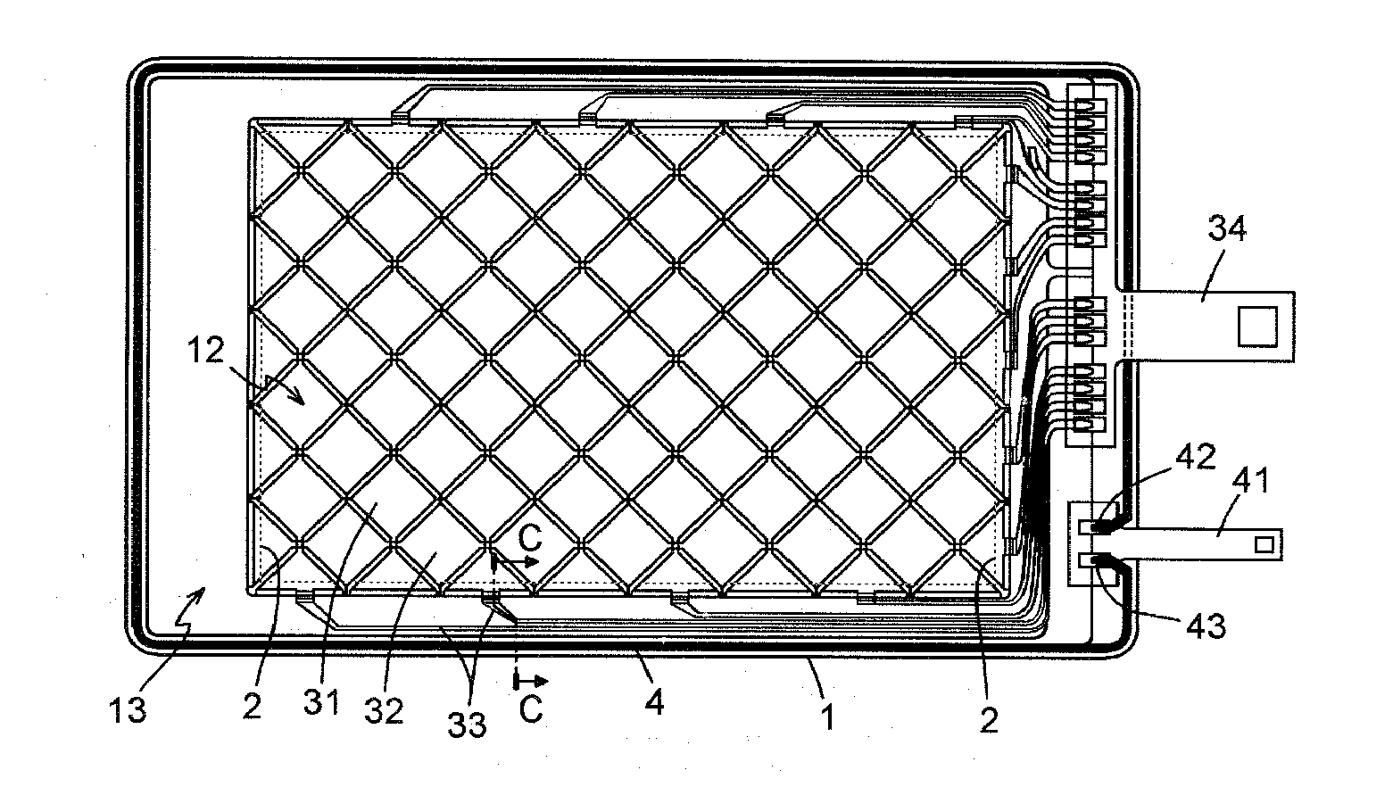
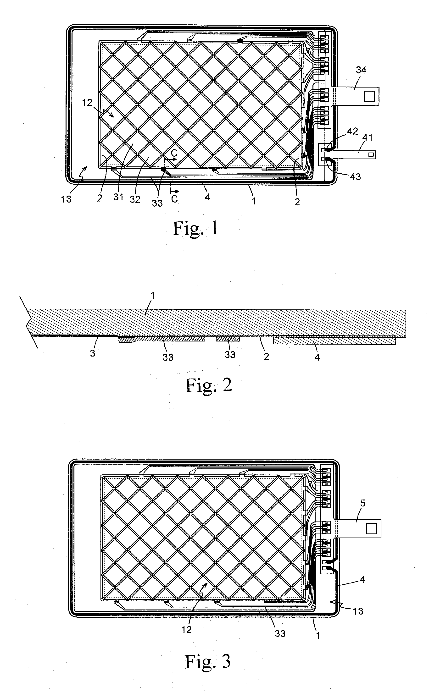
[0010]Referring to FIGS. 1 and 2, a preferable embodiment according to present invention is illustrated. The multi-function touch panel includes a substrate 1, color frame 2, transparent touch sensing unit 3, and a flat antenna 4. The substrate 1 is a transparent thin plate of high mechanical strength such as a plate of glass, polymethylmethacrylate (PMMA), Polycarbonate (PC), Polythylene terephthalate (PET), or Cyclic Olefin Copolymer (COC). The substrate 1 could be a soft or hard plate made of other material. The substrate 1 is a flat plate havin...


PUM


Abstract

A multi-function touch panel includes a transparent substrate and an opaque color frame formed by an edge of the substrate so as to form a visible area and a shelter area on the substrate. A transparent touch sensing unit is formed to the visible area on a surface of the substrate. A signal wiring under the shelter area is formed around the touch sensing unit. The signal wiring is electrically connected between the touch sensing unit and a first signal bus. A flat antenna is insulatedly formed outside the signal wiring under the shelter area. Two ends of the flat antenna are electrically connected to a second signal bus. The color frame is made of insulated material. The first signal bus and the second signal bus are integrated as one signal bus.

Description

FIELD OF THE INVENTION[0001]The present invention relates to touch panel, and particular to a multi-function touch panel capable of transmitting and receiving wireless signal.DESCRIPTION OF THE PRIOR ART[0002]Wireless communication technology is widely applied to various electronic devices. For the portable electronic devices, the wireless communication could be an essential. Except the functions and accessories, the outer appearances are also an important part for the portable devices such as mobile phone, laptop, or tablet PC. Therefore, the antenna for wireless communication of such device is hidden from the case. However, the hidden antenna also has difficulties of limitation in interior space and metal interference. To prevent shield effect by metal case, some device will use plastic or non-metal case instead of metal case so that the mechanical strength, endurance, and the anticorrosive must be sacrificed. To compromise between the visual fineness and shield effect of metal, s...

Claims


Application Information

Patent Timeline
IPC IPC(8): G06F3/045G06F3/041
CPCG06F3/044H01Q7/00H01Q1/44H01Q1/243G06F3/0445G06F3/0446
Inventor CHEN, SHENG-HSIUNG
Owner LUMINOUS OPTICAL TECH
Why Eureka
Try Eureka