Method of constructing core with tapered pole pieces and low-loss electrical rotating machine with said core

Active Publication Date: 2013-02-21
GLASSY METAL TECH
View PDF11 Cites 5 Cited by
  • Summary
  • Abstract
  • Description
  • Claims
  • Application Information

AI Technical Summary

Benefits of technology

[0016]In accordance with an embodiment of the invention, the electrical rotating machine exhibits advantages that include the

Problems solved by technology

However, there is a limit to the smallest gap as the rotor spins while the stator is stationary.
Thus a certain amount of the energy stored in the gap is lost, resulting in an energy loss.
However, the '694 patent does not provide substantial improvement of the rotating machine efficiency.
Although

Method used


Image

  • Method of constructing core with tapered pole pieces and low-loss electrical rotating machine with said core
  • Method of constructing core with tapered pole pieces and low-loss electrical rotating machine with said core
  • Method of constructing core with tapered pole pieces and low-loss electrical rotating machine with said core

Examples


Example

Example 1

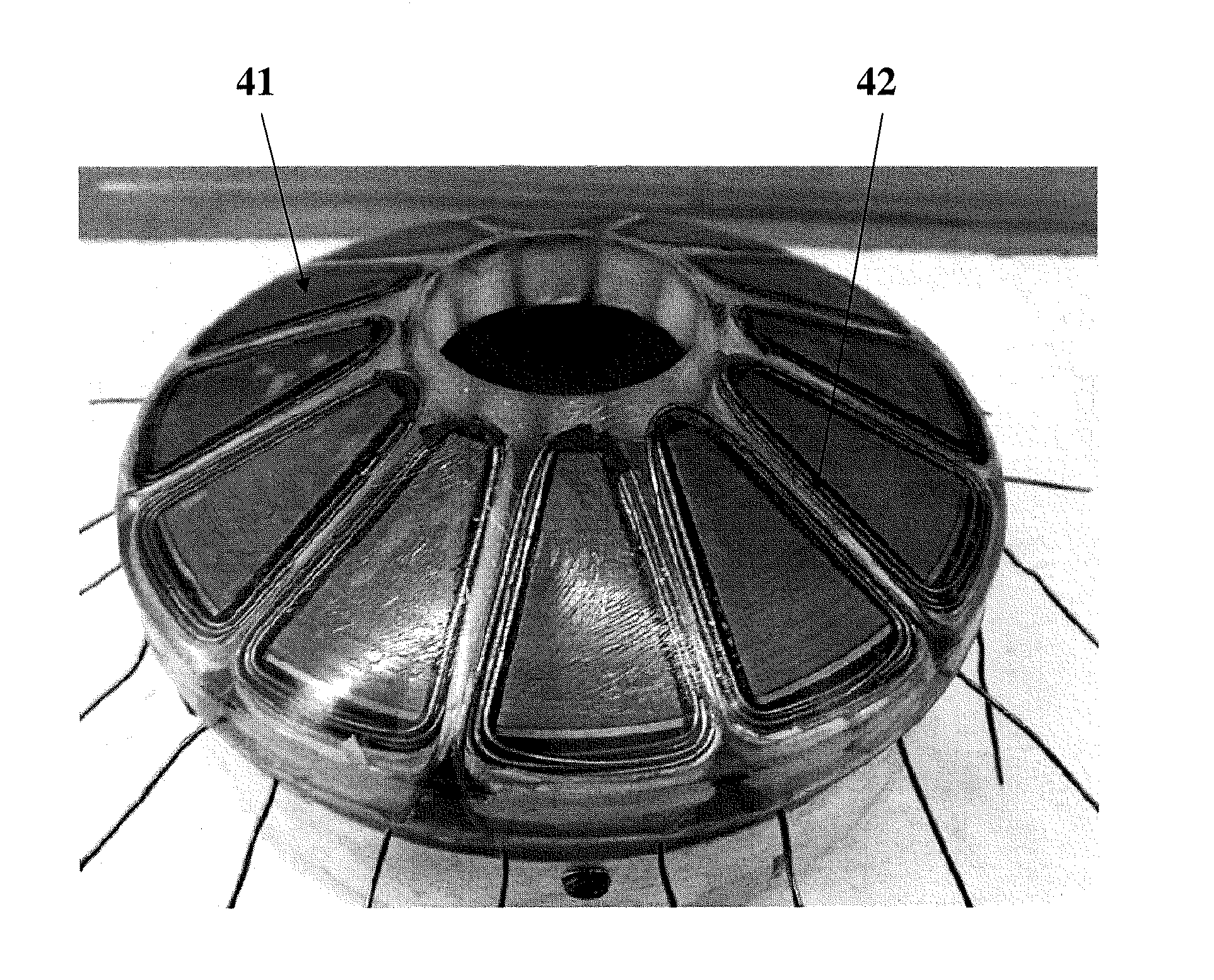
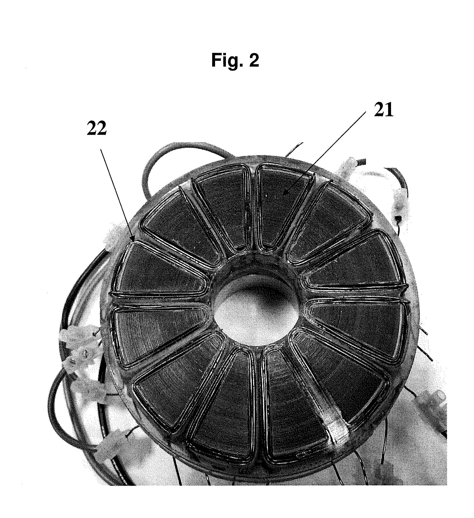
[0042]A motor stator core of an embodiment of the present invention as depicted in FIG. 4 had an outside diameter D=110 mm, an inside diameter d=45 mm, a plurality of pole pieces each with an outside width of to=21 mm and an inside width of ti=38 mm, a plurality of slots each with a slot width s=8 mm, pi=30 mm, slot depth sd=12 mm and a pole piece surface having a taper angle φ=29 degrees. A stator core of conventional configuration as depicted in FIG. 2 had the same physical dimensions as those in FIG. 4, except that the taper angle φ=0.

[0043]The motors with stators of FIG. 2 and FIG. 4 were tested in accordance with a conventional dynamometer test method. FIG. 5 compares the output torque versus the motor speed given by curve 52 for a motor of an embodiment of the present invention and that for a conventional motor given by curve 51. From the two curves, 52 and 51, higher output torque was realized as the motor speed increased by adopting a stator core of that embodiment ...

Example

Example 2

[0047]The following stator core sizes were different from those in Example 1, and were examined and evaluated. The dimension designations were the same as those in FIG. 3.

[0048]Core A: D=110 mm, d=45 mm, sd=17 mm, φ=25 degrees, and pi=30 mm. Core B: D=110 mm, d=45 mm, sd=12 mm, φ=25 degrees, and pi=30 mm. Core C: D=60 mm, d=40 mm, φ=20 degrees, and pi=30 mm. All of these stator cores had twelve (12) slots and ten (10) poles.

[0049]As shown in FIG. 9, stator Core A showed higher efficiency than stator Core B at all torque levels. Above 1 Nm of torque, Cores A and B reach efficiencies of 90% and 80%, respectively.

[0050]In FIG. 10, motor torque as a function of motor speed was compared among stator Cores A, B and C. These examples indicated that stator core configurations affected the overall motor efficiency. The general trend was: larger cores with higher degree of pole surface taper angle resulted in higher motor torque and efficiency for a given motor speed.

[0051]For exampl...


PUM

PropertyMeasurementUnit
Efficiencyaaaaaaaaaa

Abstract

An electrical rotating machine having a stator or a rotor with a core that includes a plurality of tapered pole pieces is a low loss electrical machine that results in improvements such as higher output power, higher torque and higher efficiency than a machine that does not have tapered pole pieces. The stator or the rotor with tapered pole pieces may be applied to a power train in automobiles, power tools, and various appliances. A method of constructing the core includes winding an iron-based amorphous magnetic alloy ribbon to form a cylinder-shaped core, then heating, impregnating with resin, and machining the cylinder-shaped core to form a plurality of tapered pole pieces being separated in an alternating manner by a plurality of slots. The cores having an outside diameter in a range of 50 mm-1200 mm, a tapered angle in a range of 10°-45°, and a slot depth in a range of 10 mm-210 mm are advantageous.

Description

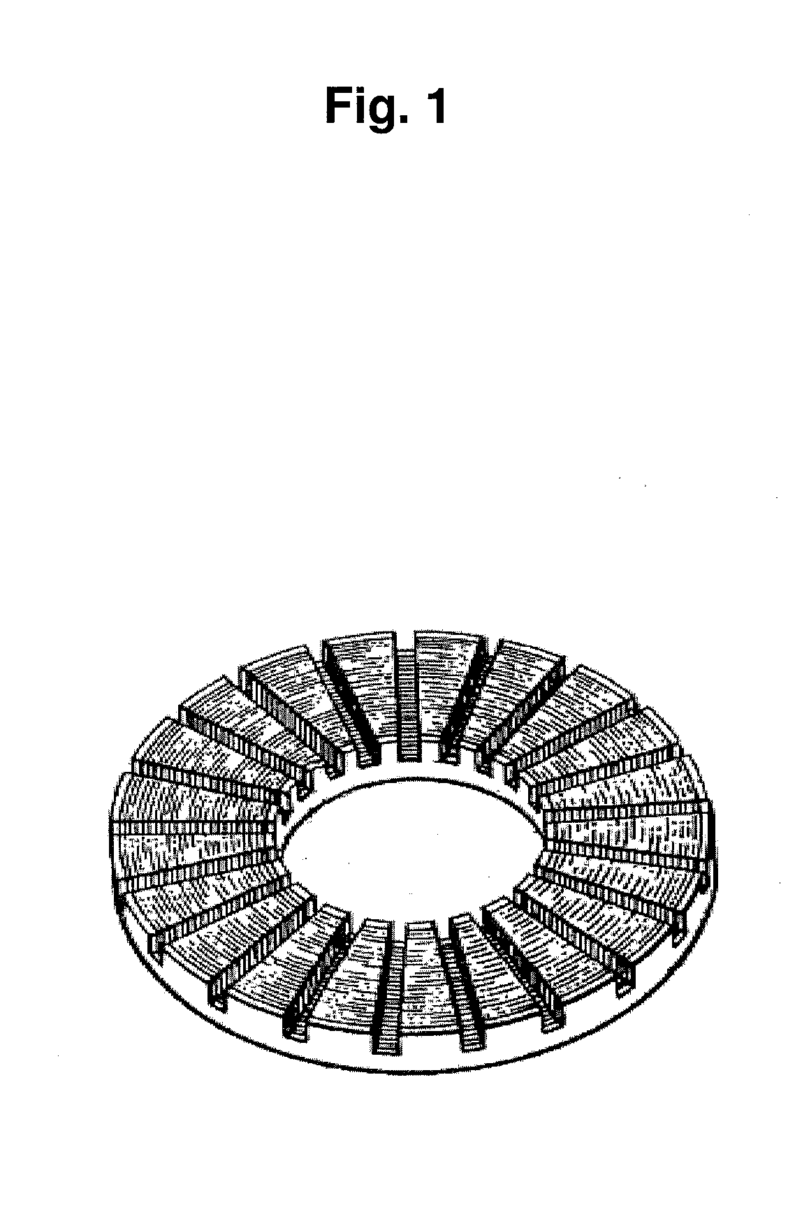
BACKGROUND[0001]1. Field[0002]Embodiments of the invention relates to axial magnetic flux electric rotating machines such as motors and generators, and more particularly to such machines in which flux line penetration between stators and rotors is made more effective than in conventional machines.[0003]2. Description of the Related Art[0004]As described in U.S. Pat. No. 2,469,808, development of axial magnetic flux electrical rotating machines started with a stator core with a pancake design. The inefficient design was changed as described in U.S. Pat. No. 4,394,597 (hereinafter the '597 patent). The core configuration taught in the '597 patent, as shown in FIG. 1, could be used either as a stator or a rotor. The core of FIG. 1 is featured with a flat annular surface and slotted section into which electrical conductor windings are placed. The annular flat surface of the rotor has a counterpart flat surface of a stator arranged in such a manner that the two flat surfaces are parallel...

Claims


Application Information

Patent Timeline
IPC IPC(8): H02K15/12H02K15/08H02K1/16
CPCH02K21/24H02K2201/03Y10T29/49009H02K15/026Y10T29/49012H02K15/022H02K15/12H02K2213/03H02K1/16
Inventor GAYLER, JOHN ANDREWKLOEDEN, STEPHEN ROBERTERTUGRUL, NESIMIHASEGAWA, RYUSUKE
Owner GLASSY METAL TECH
Why Eureka
Try Eureka