Driving apparatus and stop position detection method

a technology of stop position and detection method, which is applied in the direction of electronic commutators, ac motor direction control, dynamo-electric converter control, etc., can solve the problems of large current flow through, impaired and inability to obtain signals sufficient to detect the position of the rotor, etc., to suppress the power supply voltage temporarily reduced, the effect of maintaining the stability of the power supply apparatus

Inactive Publication Date: 2013-02-21
MITSUBA CORP
View PDF7 Cites 24 Cited by
  • Summary
  • Abstract
  • Description
  • Claims
  • Application Information

AI Technical Summary

Benefits of technology

[0008]The present invention has been made in view of the above-described circumstances, and an object of the invention is to provide a driving apparatus and a stop position detection method, which can reduce a load on a power supply apparatus that supplies power to a motor in detection of a position of a rotor when driving of a motor is started.
[0014]According to the above-described aspects of the present invention, the energization pattern determination unit designates a duty ratio at which ON and OFF of each switching element provided in the inverter unit are switched as the duty ratio corresponding to the value of the maximum current capable of being supplied by the power supply apparatus. Thereby, when the position at which the rotor stops is detected if driving of the motor is started, a load on a power supply apparatus can be reduced to a fixed level or less, and the stability of the power supply apparatus can be maintained. As a result, it is possible to suppress a voltage of power supplied by the power supply apparatus being temporarily reduced.

Problems solved by technology

Incidentally, there is a possibility that a signal sufficient for detecting the position of the rotor is not obtained because the induced voltage is not generated or is very low when the number of rotations is zero or very small such as when driving of the brushless motor is started.
However, in technology disclosed in Japanese Patent Application Publication No. 2009-071926, there is a possibility that a large current flows through the coil if magnetic saturation occurs when the voltage is applied to coil of each phase.
In this case, there is a possibility that, due to a load on a power supply apparatus such as a storage battery that supplies power to the motor, the stability of the power supply apparatus is impaired such as a voltage of power to be supplied by the power supply apparatus is temporarily reduced.

Method used


Image

  • Driving apparatus and stop position detection method
  • Driving apparatus and stop position detection method
  • Driving apparatus and stop position detection method

Examples


Embodiment Construction

[0028]Hereinafter, a driving apparatus and a stop position detection method according to the present embodiment will be described with reference to the drawings.

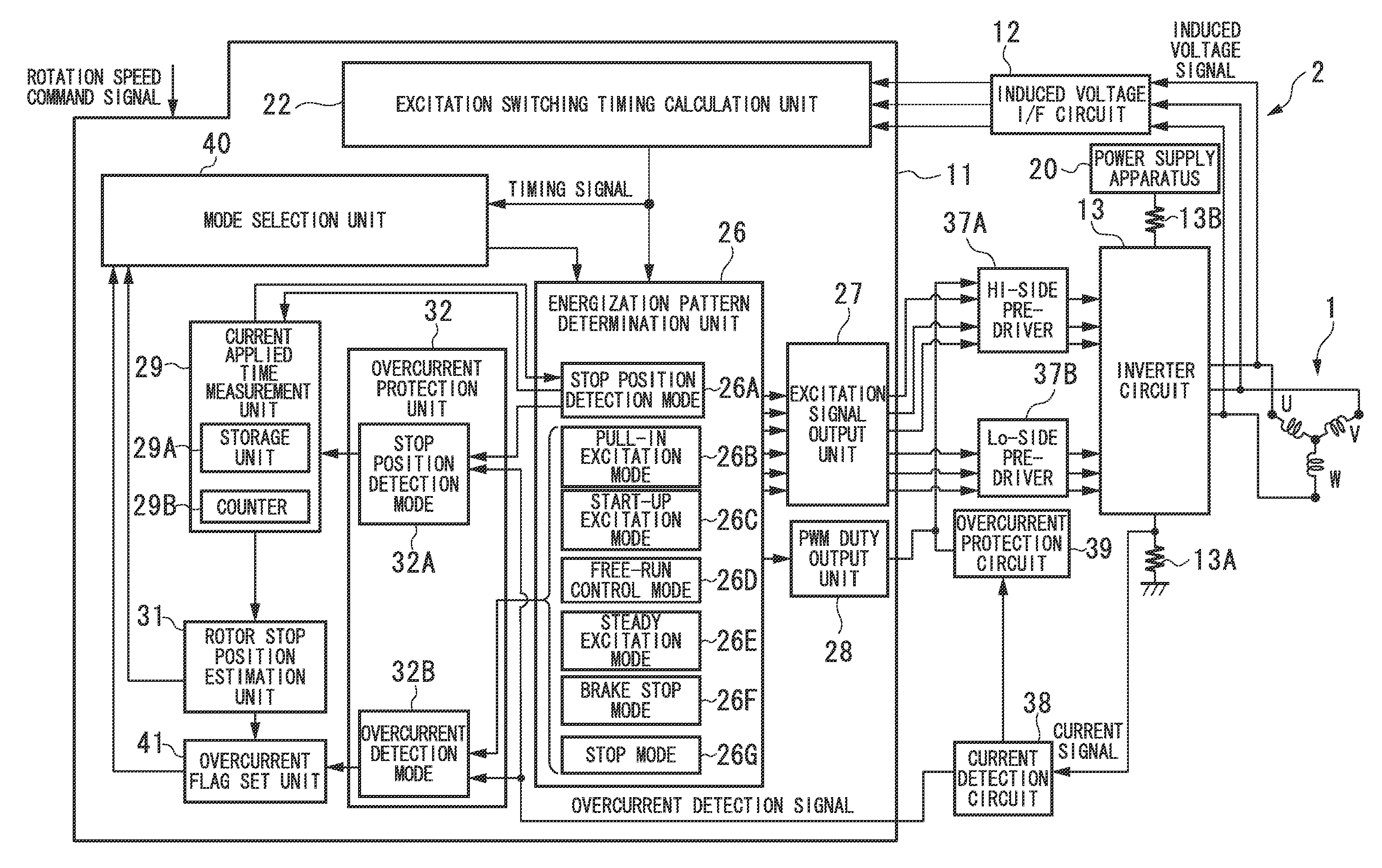
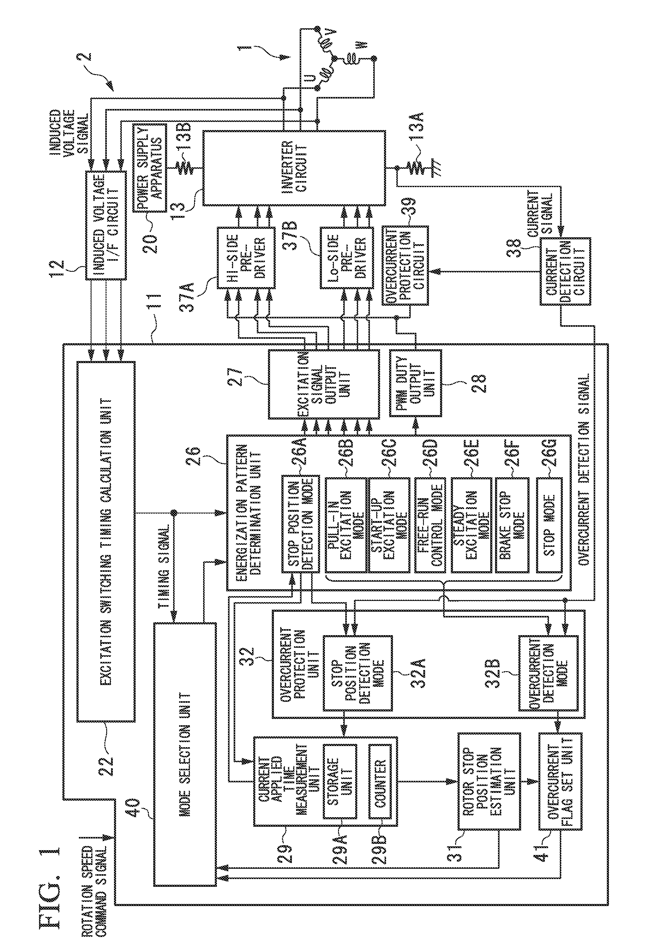
[0029]FIG. 1 is a schematic block diagram illustrating a configuration of a motor system according to the present embodiment. As illustrated in FIG. 1, the motor system includes a brushless motor 1 and a driving apparatus 2 that controls driving of the brushless motor 1.

[0030]The brushless motor 1 is a sensorless type motor in which there is no sensor that detects a position of a rotor provided in the brushless motor 1. The brushless motor 1 includes the rotor having a permanent magnet and a stator. Coils U, V, and W corresponding to three phases U, V, and W are sequentially wound around the stator in a circumferential direction. The coils U, V, and W of each phase have one ends connected to the driving apparatus 2 via motor terminals and the other ends connected to each other.

[0031]The driving apparatus 2 includes a control...


PUM


Abstract

A driving apparatus including an inverter unit for energizing the coil by switching ON and OFF of the switching element, an energization pattern determination unit for selecting a plurality of energization patterns, each of which indicates a direction of a current that flows through the coil, one by one when driving of a motor is started, and energizing the coil by switching ON and OFF of the switching element based on a selected energization pattern at a duty ratio corresponding to a value of a maximum current capable of being supplied by the power supply apparatus, a current applied time measurement unit for measuring an energization time, which is a time until a value of the current flowing through the coil reaches a predetermined target current value for each energization pattern, and a rotor stop position estimation unit for estimating a position at which the rotor stops.

Description

BACKGROUND OF INVENTION[0001]1. Field of Invention[0002]The present invention relates to a driving apparatus and a stop position detection method.[0003]This application claims priority to and the benefit of Japanese Patent Application No. 2011-124249, filed on Jun. 2, 2011, the disclosure of which are incorporated by reference herein.[0004]2. Description of Related Art[0005]As a brushless motor in which a rotor has a permanent magnet, there is a brushless motor in which driving control is performed in position-sensorless without a position sensor for detecting a position (angle) of the rotor. In this case, the position of the rotor is detected from an edge interval of a pulse signal obtained by inputting an induced voltage, which appears at a motor terminal of an open section (non-energized phase), and an equivalent neutral-point potential to a comparator. Incidentally, there is a possibility that a signal sufficient for detecting the position of the rotor is not obtained because th...

Claims


Application Information

Patent Timeline
Patent Type & Authority Applications(United States)
IPC IPC(8): H02P6/16H02P6/06H02P6/18H02P6/08H02P6/182
CPCH02P6/002H02P23/0072H02P6/182H02P23/24H02P6/28
Inventor SHIBUYA, SHINJIIWAZAKI, TAMOTSUHINO, SADAMI
Owner MITSUBA CORP
Why Eureka
Try Eureka