Image display method and apparatus

a technology of image display and fluorescence image, applied in the field of image display methods and apparatuses, can solve the problems of inobservable surrounding region of light output portion, inability to accurately recognize where the light output portion of fluorescence image is located in the ordinary image, and inability to accurately represent information, etc., to accurately recognize the light output portion. the effect of the location

Active Publication Date: 2013-02-21
FUJIFILM CORP
View PDF11 Cites 21 Cited by
  • Summary
  • Abstract
  • Description
  • Claims
  • Application Information

AI Technical Summary

Benefits of technology

This patent is about a new method and device for displaying images that can show where the light is coming from in a scene. This is important because it helps to accurately identify and represent information about the brightest areas in the image. The method involves using special light that is different from visible light to illuminate the scene and create a special image. Then, a part of that special image is taken and combined with the visible image to create a superimposition image. This can be useful for identifying and measuring the brightness of different areas in a scene.

Problems solved by technology

Therefore, when the fluorescence image is observed alone, the light output portion of the region to be observed may be observed, but a surrounding region of the light output portion is not observable.
Hence, it is impossible to recognize where the light output portion is located in the region to be observed.
However, since the two images are displayed separately, it is still impossible to accurately recognize where the light output portion of the fluorescence image is located in the ordinary image.
However, when a synthesis image is generated by combining an ordinary image and a fluorescence image together, as in Patent Documents 1 through 5, there is a risk that necessary information becomes unobtainable because it becomes difficult to observe the gradation or the like of the light output portion of the fluorescence image.
Hence, a cost for production increases, and the size of the apparatus becomes large.

Method used


Image

  • Image display method and apparatus
  • Image display method and apparatus
  • Image display method and apparatus

Examples


Embodiment Construction

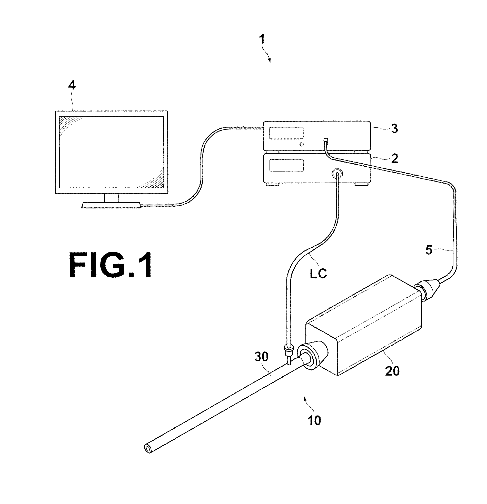
[0039]Hereinafter, a rigid endoscope system using an image display apparatus according to an embodiment of the present invention will be described in detail with reference to drawings. FIG. 1 is a schematic external view illustrating the structure of a rigid endoscope system 1 according to an embodiment of the present invention.

[0040]As illustrated in FIG. 1, the rigid endoscope system 1 of the present embodiment includes alight source apparatus 2, a rigid endoscope imaging apparatus 10, a processor 3, and a monitor 4 (corresponding to a display unit). The light source apparatus 2 outputs ordinary light of white light and excitation light. The rigid endoscope imaging apparatus 10 guides ordinary light and excitation light output from the light source apparatus 2, and illuminates a region to be observed with the ordinary light and the excitation light. Further, the rigid endoscope imaging apparatus 10 images an ordinary image based on reflection light that has been reflected from the...


PUM


Abstract

A visible image based on light output from a region to be observed by illumination of the region to be observed with visible light, and a special image based on light output from the region to be observed by illumination of the region to be observed with special light in a wavelength band that is different from the wavelength band of the visible light are obtained. An extraction image is generated by extracting a part of image data representing the visible image. A superimposition image is generated by superimposing the generated extraction image on the special image. The generated superimposition image is displayed.

Description

BACKGROUND OF THE INVENTION[0001]1. Field of the Invention[0002]The present invention relates to an image display method and apparatus for displaying a special image of a region to be observed obtained by illumination of the region to be observed with special light.[0003]2. Description of the Related Art[0004]Conventionally, endoscope systems for observing tissues in patients' body cavities were widely known. Further, electronic endoscope systems that obtain ordinary images of regions to be observed in patients' body cavities by illuminating the regions with white light, and that display the ordinary images on monitor screens were widely used in practical applications.[0005]As such endoscope systems, for example, a fluorescence endoscope system that obtains an autofluorescence image as well as an ordinary image, and that displays the two images on a monitor screen has been proposed. The fluorescence endoscope system obtains the autofluorescence image by imaging an image of autofluor...

Claims


Application Information

Patent Timeline
Patent Type & Authority Applications(United States)
IPC IPC(8): G09G5/00
CPCH04N7/183A61B1/043G02B23/2453G06T2207/20221G06T5/50G06T2207/10064G06T2207/10068G02B27/1013
Inventor YAMADA, HIDEYUKI
Owner FUJIFILM CORP
Why Eureka
Try Eureka