Integrated Advanced Heat Spreader for Solid-State Laser Systems
a heat spreader and solid-state laser technology, applied in semiconductor lasers, paper/cardboard containers, containers, etc., can solve the problems of unsatisfactory conditions and the inability to direct jet impingement cooling of thin disks, and achieve the effect of improving the performance of thin disk lasers
- Summary
- Abstract
- Description
- Claims
- Application Information
AI Technical Summary
Benefits of technology
Problems solved by technology
Method used
Image

Examples
second embodiment
[0115]This embodiment comprises use of either a square or rectangular array of parallel oscillating heat pipes configured very close to each other to create a near isothermal condition on the heat spreader top surface at high power including greater than kW's / cm2. FIGS. 24-a and 26 illustrate square / rectangular linear array system for a very high thermal conductivity heat spreader for use with a high power, good operating thin disk laser system. The thin disk 1 and / or 899 is mounted on the oscillating closed loop heat pipe 2 and / or 41, which is internally integrated and coupled with ports 48 and 45 to the working fluid pump not shown. FIG. 26-b shows this linear array advanced heat spreader system (hereafter AHS system) consisting of the top 54, two sides 51 and 55 and the inlet coolant connection 52 and outlet connection 79 for heat removal from the integrated advanced heat spreader system 982 in FIG. 20-b. The coolant can be water or liquid coolants like acetone, ammonia or nitrog...
third embodiment
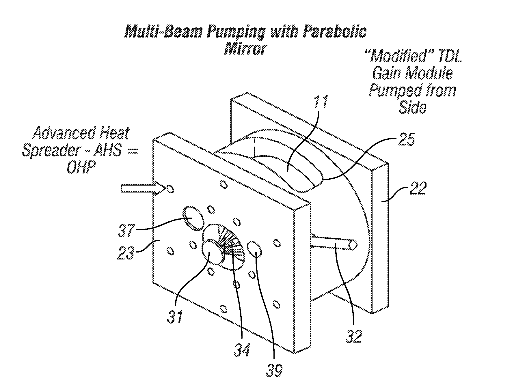
[0120]The previous embodiment of the use of a square or rectangular configured, high power heat spreader with prior art thin disk laser requires changes in the gain module 25 design illustrated in FIG. 25. This embodiment of the invention offers an alternative, namely a circular configured system that can be inserted into the “present-day” thin disk laser designs as shown in FIG. 24-b. FIG. 24-b depicts such a circular or round advanced heat spreader with a circular lasing thin disk 171. The embodiments and its other versions can be readily made to operate as a lasing thin disk 24 performs shown in FIG. 25-b and is nearly inside the backside plate 23. FIG. 27-a shows the various parts of this new embodiment which consists of the lasing thin disk 172, an alternative OHP based heat spreader 103, a coolant chamber 105 removing the thermal heat from the heat spreader 103 which has a top plate 102 and lower plate 104. In addition, this heat spreader system is integrated with fluid pump 1...
fourth embodiment
[0123]This embodiment is close to the previous third embodiment but the changes can provide significant improvement by providing improved isothermal temperature profile across the thin disk. Important to note that the many main OHP slot paths 121,120,130,122 and 121 all have a direct path toward the outer return holes down to the bottom side of the heat spreader 103 shown in FIGS. 27-c and 27-d. This condition can create less flow into the main “spoke” arms originating from these main slot pathways. In FIG. 28-a and 28-b, these return holes like 130 in FIG. 27-c and 27-g were removed thus forcing the working fluid to always return through the cited “side spokes” via exit hole 210. All of the additional operation is like that described in FIG. 27.
[0124]Again, like the above third embodiment, the important features of this embodiments is its circular design, potential compact size and future direct insertion into present thin disk laser systems. The multiple pathways for the OHP proce...
PUM
| Property | Measurement | Unit |
|---|---|---|
| Temperature | aaaaa | aaaaa |
| Power | aaaaa | aaaaa |
| Phase | aaaaa | aaaaa |
Abstract
Description
Claims
Application Information
 - R&D Engineer
- R&D Manager
- IP Professional
- Industry Leading Data Capabilities
- Powerful AI technology
- Patent DNA Extraction
Browse by: Latest US Patents, China's latest patents, Technical Efficacy Thesaurus, Application Domain, Technology Topic.
© 2024 PatSnap. All rights reserved.Legal|Privacy policy|Modern Slavery Act Transparency Statement|Sitemap