Dual Backplate Microphone

a backplate microphone and microphone technology, applied in the field of microphones, can solve the problems of significant high production volume commercial applications of this type of microphon

Inactive Publication Date: 2013-02-21
HARMAN INT IND INC
View PDF7 Cites 50 Cited by
  • Summary
  • Abstract
  • Description
  • Claims
  • Application Information

AI Technical Summary

Benefits of technology

[0013]A further understanding of the nature and advantages of the present invention may be realized by reference to the remaining portions of the specification and the drawings.

Problems solved by technology

Unfortunately, both structural and electrical interconnection difficulties have prevented significant high production volume commercial applications of this type of microphone.

Method used


Image

  • Dual Backplate Microphone
  • Dual Backplate Microphone
  • Dual Backplate Microphone

Examples


Embodiment Construction

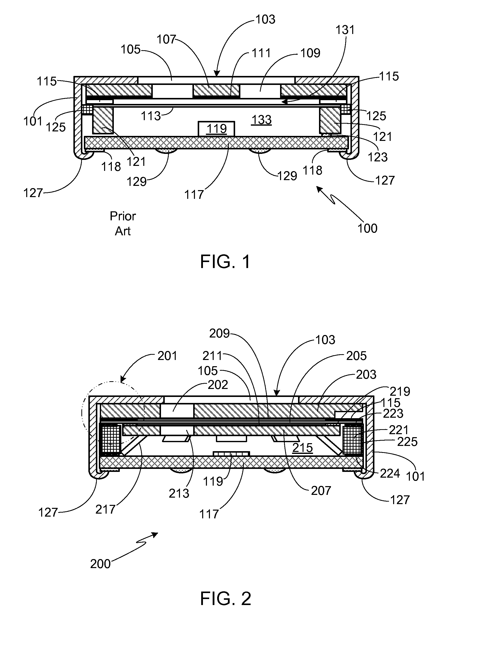
[0034]FIG. 1 illustrates the basic elements of a conventional electret microphone, often referred to as a single-sided electret microphone. As shown in this cross-section, microphone 100 includes an electrically conductive, cylindrical casing 101, also referred to as a ferrule. In a typical microphone, ferrule 101 has a diameter of between 3 and 10 millimeters. The front face 103 of an end portion of casing 101 includes one or more, substantially co-located, acoustic apertures 105. An electrode plate 107 with one or more secondary acoustic apertures 109 fits against the inner surface of front portion 103 of casing 101. An electret material 111 is deposited on, or otherwise applied to, the inner surface of electrode 107 and charged. A metallized polymer diaphragm 113 is separated from electret material layer 111 by an electrically insulating spacer 115.

[0035]A printed circuit board (PCB) 117 fits within, and covers, the casing opening located at the distal end opposite front face 103...


PUM


Abstract

A dual backplate microphone is provided that utilizes either an electret condenser or a MEMS condenser configuration and in which an op-amp IC is electrically connected to both backplates and the conductive layer of the diaphragm.

Description

CROSS-REFERENCE TO RELATED APPLICATION[0001]This application claims the benefit of the filing date of U.S. Provisional Patent Application Ser. No. 61 / 523,426, filed 15 Aug. 2011, the disclosure of which is incorporated herein by reference for any and all purposes.FIELD OF THE INVENTION[0002]The present invention relates generally to microphones and, more particularly, to a dual backplate microphone.BACKGROUND OF THE INVENTION[0003]There is a great need to continually improve the signal-to-electrical noise ratio (SNR) of audio microphones such as electret condenser microphones (ECM), MEMS condenser microphones, and MEMS with electret biasing microphones. The electrical noise in variable capacitive microphones of this type is largely determined by the amplifier integrated circuit (IC) contained within the microphone case or package. As such, it is critical to optimize the audio signal level arriving at the input of the IC from the microphone's acoustic-to-electrical capacitive transdu...

Claims


Application Information

Patent Timeline
Patent Type & Authority Applications(United States)
IPC IPC(8): H04R19/04H04R19/01H04R3/00
CPCH04R3/005H04R2410/03H04R19/016H04R19/005
Inventor BARBER, JOSHUA R.BAUMHAUER, JR., JOHN CHARLESMCATEER, JEFFREY PHILLIPMICHEL, ALAN DEANOLSON, JAMES V.
Owner HARMAN INT IND INC
Why Eureka
Try Eureka