

Dental implant fixing system
- Summary
- Abstract
- Description
- Claims
- Application Information
AI Technical Summary
Benefits of technology
Problems solved by technology
Method used
Image

Examples
first embodiment
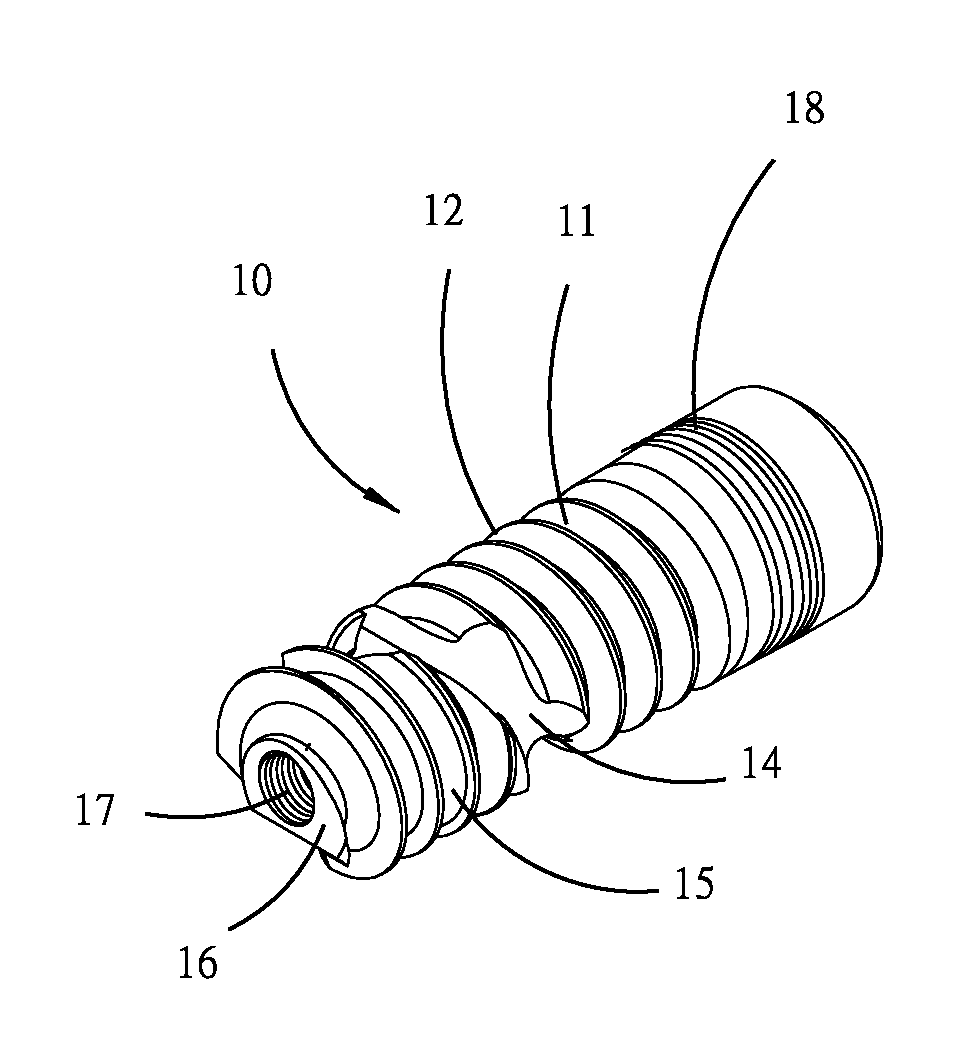
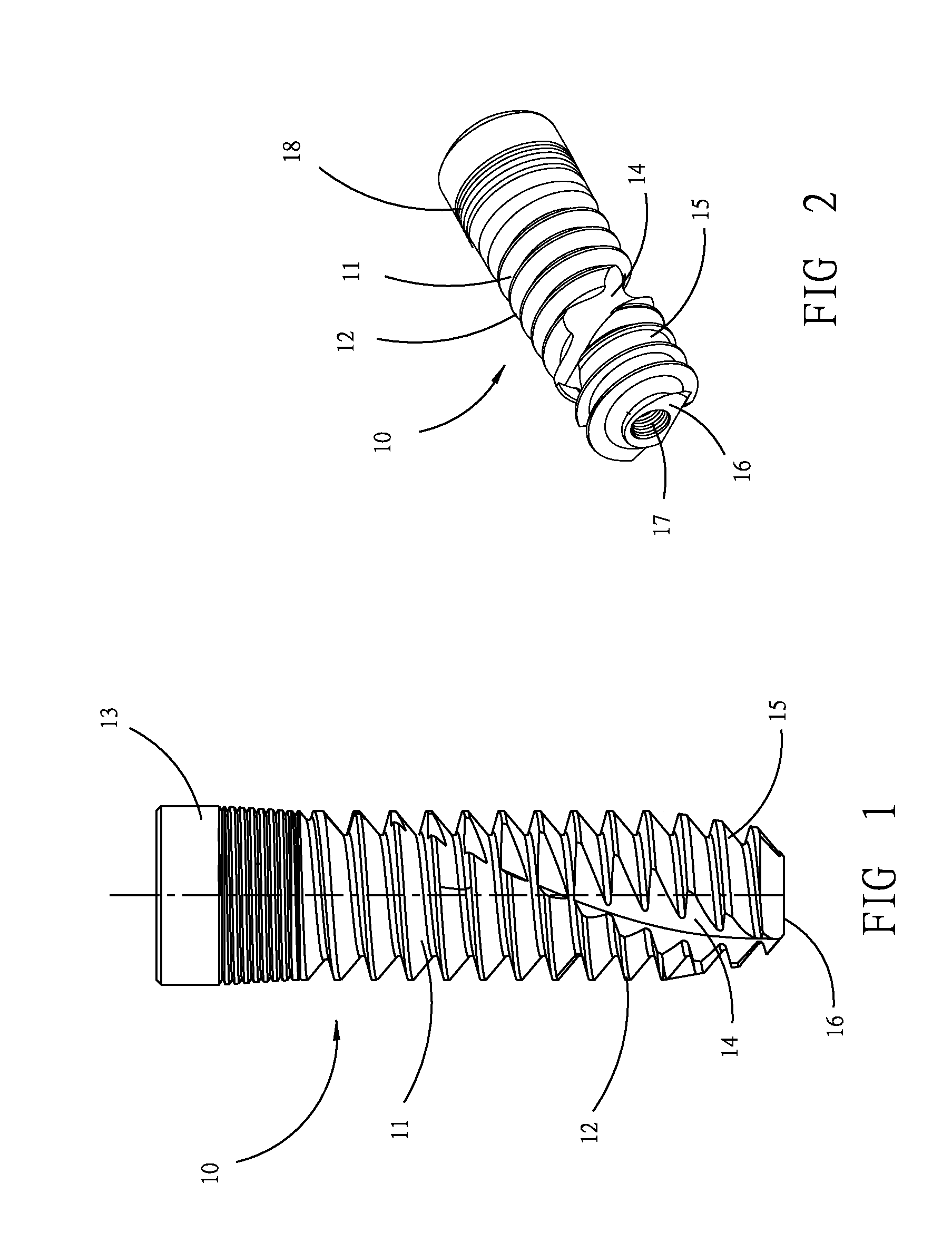
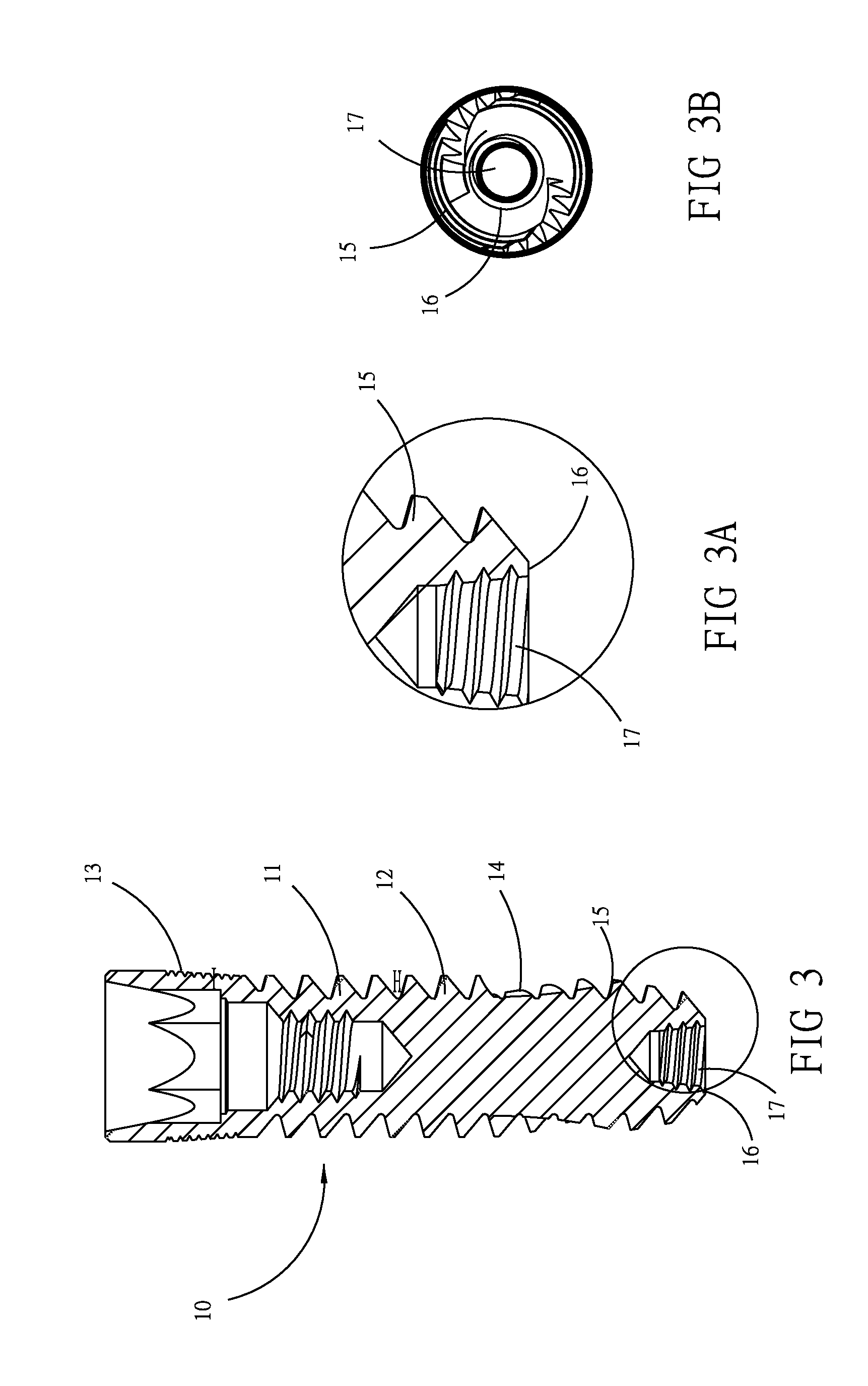
[0021]FIGS. 1-4 show the dental implant fixing system of the present invention, which comprises an implant 10 in a cylindrical shape. Defined by the implanting direction into an oral alveolar bone 40, the implant 10 has an upper part and a bottom part. The bottom part of the implant 10 is a main body 11 in cylindrical shape, having a thread division 12 outside, for engaging with the alveolar bone, while the upper part has a neck part 13 with line thread 18 outside. At the same time, the neck part 13 is jointed with an abutment 20 on top, which is mounted with a prosthetic tooth 30 over the implant 10 (as shown in FIG. 4).
[0022]As shown in FIG. 2, the thread division 12 has an end part 15 at the bottom as a self-tapping thread. At least one groove 14 extending outside from the end part 15 to the main body 11 is set on the thread division 12, for easily engaging with the tissue of the alveolar bone. Further, the groove 14 can hold bone chips caused by cutting the alveolar bone with th...
second embodiment
[0029]FIG. 5 shows the present invention, which is applied to monobloc implant, wherein the implant 10A is in one piece combined with the abutment 20 to fix prosthetic tooth. The implant 10A comprises at bottom a main body 11A, connecting an end part 15A beneath. Outside the main body 11A and the end part 15A there is thread division 12A. A conial screw 17A is set at center of the lower end 16A of the end part 15A.
[0030]The second as well as the first embodiment of the present invention have the same characteristics, that is, the thread division 12A, main body 11A, end part 15A, conial screw 17A, lower end 16A have the same characteristics as the thread division 12, main body 11, end part 15, conial screw 17 and lower end 16, respectively. Accordingly, their description is omitted.
PUM
 Abstract
Description
Claims
Application Information