

Automatic analysis device and automatic analysis method
a technology of automatic analysis and analyzer, which is applied in the direction of material analysis, measurement devices, instruments, etc., can solve the problems of insufficient amount of substrates in reagents during measurement, inconstant reaction rate in second half, and shortening measurement time period, so as to achieve the effect of shortening the time required to determine a line rang
- Summary
- Abstract
- Description
- Claims
- Application Information
AI Technical Summary
Benefits of technology
Problems solved by technology
Method used
Image

Examples
embodiments
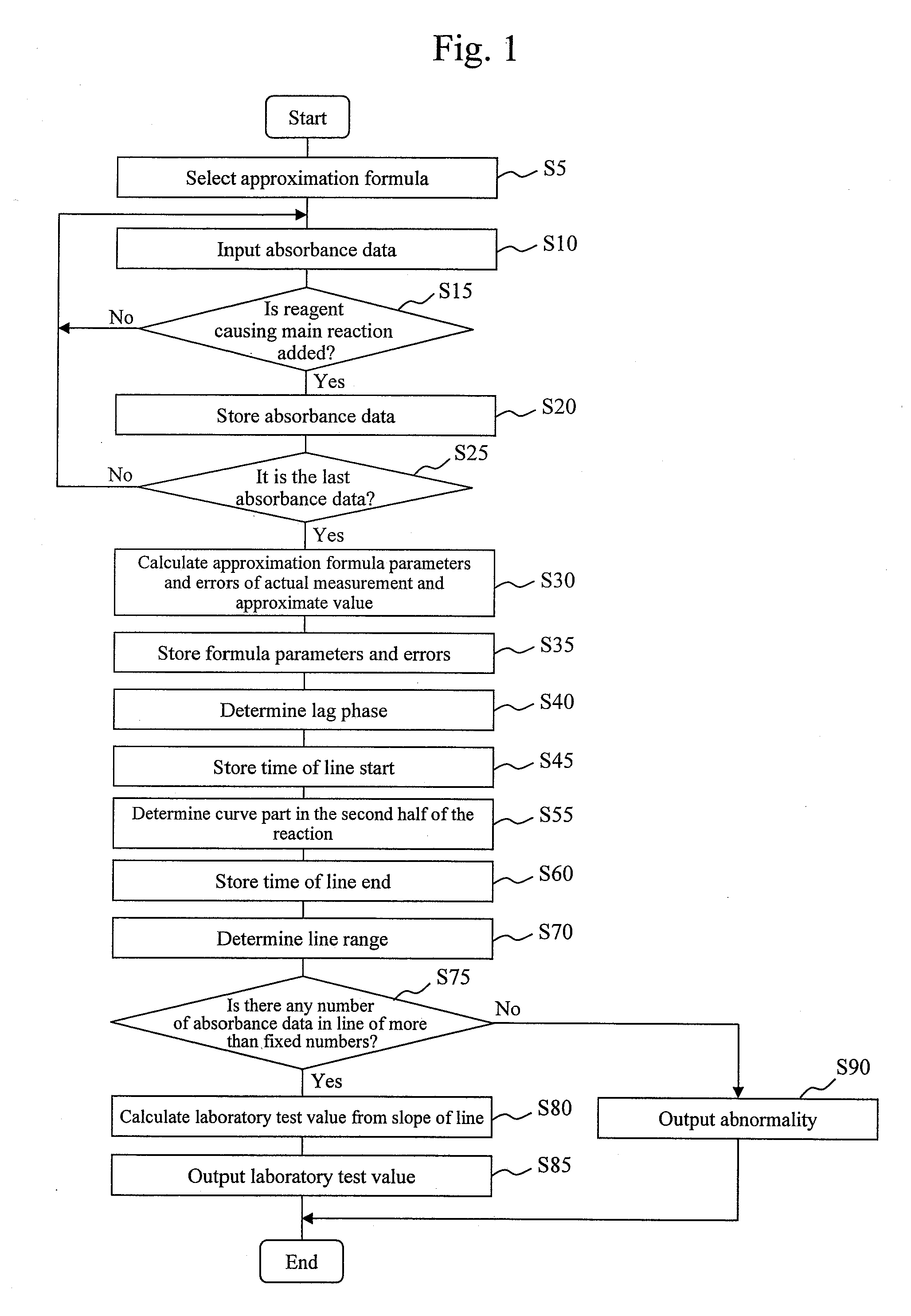
First Embodiment
[0042]The system configuration and processing operation of an automated analyzer according to a first embodiment will be described below in detail with reference to the drawings. FIG. 3 shows the schematic configuration of a biochemical automated analyzer equipped with an analysis function according to the present invention.
[0043]The biochemical automated analyzer includes a sample disc 1, a reagent disc 2, a reaction disc 3, a reaction vessel 4, a sampling mechanism 5, a pipetting mechanism 6, a stirring mechanism 7, a photometry mechanism 8, a washing mechanism 9, a computer (PC) 10, a storage device 12, a control unit 13, a piezoelectric element driver 14, a stirring mechanism controller 15, a specimen container 16, circular discs 17 and 19, a reagent bottle 18, a cooling box 20, a reaction container 21, a reaction container holder 22, a drive mechanism 23, probes 24 and 27, support shafts 25 and 28, arms 26 and 29, a fixation unit 31, a nozzle 33, and a vertical...
second embodiment
[0083]An automated analyzer according to a second embodiment will be described with reference to the drawings. In the present embodiment as well, the automated analyzer is assumed to be a biochemical automated analyzer. Accordingly, the automated analyzer has the same system configuration as that of the first embodiment, i.e., the system configuration shown in FIG. 3. Operations other than the operation of a control unit 13 are the same as those in the first embodiment. A detailed description of the part other than the control unit 13 will thus be omitted.
[0084]The processing operation of the control unit 13 will be described below with a focus on a processing operation specific to the present embodiment. In the present embodiment, the control unit 13 determines a line range on the basis of the procedure shown in FIG. 11.
[0085]Note that, of the process steps in FIG. 11, ones for performing the same processing as that shown in FIG. 1 are denoted by same reference numerals.
[0086]In th...
third embodiment
[0105]An automated analyzer according to a third embodiment will be described with reference to the drawings. In the present embodiment as well, the automated analyzer is assumed to be a biochemical automated analyzer. Accordingly, the automated analyzer has the same system configuration as that of the first embodiment, i.e., the system configuration shown in FIG. 3. Operations other than the operation of a control unit 13 are the same as those in the first embodiment. A detailed description of the part other than the control unit 13 will thus be omitted.
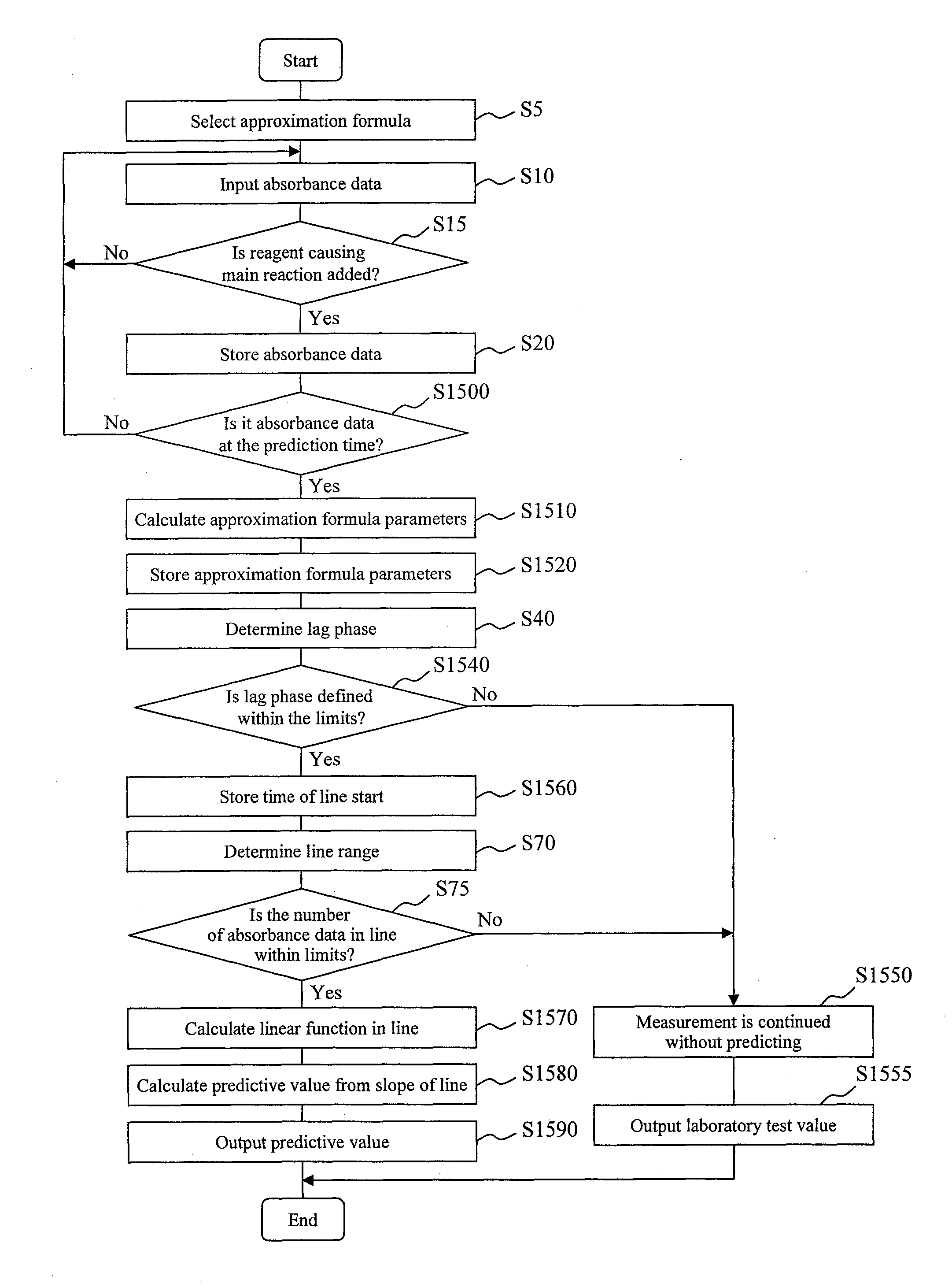
[0106]The processing operation of the control unit 13 will be described below with a focus on a processing operation specific to the present embodiment. In the present embodiment, the control unit 13 determines a line range on the basis of the procedure shown in FIG. 15. Note that, of the process steps in FIG. 15, ones for performing the same processing as that shown in FIG. 1 are denoted by same reference numerals.
[0107]In the thir...
PUM
 Abstract
Description
Claims
Application Information