Evaporator with cool storage function

a technology of evaporator and function, which is applied in the direction of indirect heat exchangers, light and heating apparatus, transportation and packaging, etc., can solve the problems of conventional evaporator in terms of cool storage performance and cool release performance, sharp drop in cooling capacity of air conditioner, and insufficient transfer through utilization of inner fins, etc., to achieve improved cool storage performance and release performance, the effect of suppressing the increase in air passage resistan

Active Publication Date: 2013-02-28
MAHLE INT GMBH
View PDF5 Cites 21 Cited by
  • Summary
  • Abstract
  • Description
  • Claims
  • Application Information

AI Technical Summary

Benefits of technology

[0009]An object of the present invention is to solve the above-mentioned problem and to provide an evaporator with a cool storage function which has improved cool storage performance and cool release performance.
[0030]According to the evaporator with a cool storage function of any one of pars. 1) to 9), each of left and right side walls of the cool storage material container has a contact portion which is in contact with the inner fin and a noncontact portion which is not in contact with the inner fin; and in an overlap region where the left and right side walls of the cool storage material container overlap with the corresponding refrigerant flow tubes when the cool storage material container is viewed from the left side or right side thereof, the area of the contact portion of each of the left and right side walls of the cool storage material container is greater than the area of the noncontact portion of each of the left and right side walls. Therefore, as compared with the evaporator with a cool storage function disclosed in the above-mentioned publication, the performance of heat transfer between the left and right side walls of the cool storage material container and the cool storage material via the inner fin becomes excellent in both the period during which cool is stored and the period during which cool is released. Accordingly, the cool storage performance and the cool release performance can be improved as compared with the evaporator with a cool storage function disclosed in the above-mentioned publication.
[0031]According to the evaporator with a cool storage function of any one of pars. 3) to 6), the following advantageous effect is achieved. Through use of a relatively simple structure, it becomes possible to enable each of left and right side walls of the cool storage material container to have a contact portion which is in contact with the inner fin and a noncontact portion which is not in contact with the inner fin. Also, in an overlap region where the left and right side walls of the cool storage material container overlap with the corresponding refrigerant flow tubes when the cool storage material container is viewed from the left side or right side thereof, the area of the contact portion of each of the left and right side walls of the cool storage material container, which portion is in contact with the inner fin, can be made greater than the area of the noncontact portion of each of the left and right side walls, which portion is not in contact with the inner fin.
[0032]According to the evaporator with a cool storage function of any one of pars. 3) and 4), the following advantageous effect is achieved. Even in the air-passing clearance in which the cool storage material container is disposed, due to presence of the convex portions, clearances are formed between the refrigerant flow tubes and the cool storage material container, and air flows through the clearances. Accordingly, an increase in air passage resistance can be suppressed. Also, the presence of the convex portions enables condensed water produced on the outer side surfaces of the refrigerant flow tubes to be drained through the clearances formed between the refrigerant flow tubes and the cool storage material container due to the presence of the convex portions.
[0033]According to the evaporator with a cool storage function of any one of pars. 5) and 6), the following advantageous effect is achieved. In the case where the refrigerant flow tubes and the cool storage material container are brazed together, the brazing area therebetween becomes smaller than that in the case where through-holes are not formed. Accordingly, the clearance—which is produced between one side of the corresponding refrigerant flow tube and the outer surface of the cool storage material container because the brazing between the two members is not performed completely over the entire surface—becomes smaller than that in the case where through-holes are not formed, and the amount of condensed water which enters the clearance also decreases. As a result, it is possible to prevent a large amount of condensed water from stagnating in the spaces between the refrigerant flow tubes and the cool storage material container and to prevent the condensed water from freezing. Thus, separation of the entire cool storage material container from the refrigerant flow tubes can be prevented for a long period of time. Moreover, at the portions of each side wall of the cool storage material container where the through-hole are formed, the cool storage material within the cool storage material container is cooled, only through the walls of the refrigerant flow tubes, by the refrigerant flowing through the refrigerant flow tubes. Therefore, the efficiency of the operation of cooling the cool storage material within the cool storage material container can be improved.

Problems solved by technology

However, an ordinary car air conditioner has a problem in that, when an engine of an automobile in which the air conditioner is mounted is stopped, a compressor driven by the engine is stopped, and supply of refrigerant to an evaporator stops, whereby the cooling capacity of the air conditioner sharply drops.
However, the evaporator with a cool storage function disclosed in the publication has the following problem.
Accordingly, in both the period during which cool is stored and the period during which cool is released, the efficiency of heat transfer between the left and right side walls of each cool storage material container and the cool storage material stored therein, which transfer is performed through utilization of the inner fin is not sufficiently high.
Therefore, the conventional evaporator is unsatisfactory in terms of cool storage performance and cool release performance.

Method used


Image

  • Evaporator with cool storage function
  • Evaporator with cool storage function
  • Evaporator with cool storage function

Examples


Embodiment Construction

[0044]An embodiment of the present invention will next be described with reference to the drawings.

[0045]In the following description, the downstream side with respect to an air-passing direction (a direction represented by arrow X in FIGS. 1, 2, 4, 6, 7, and 9) will be referred to as the “front,” and the opposite side as the “rear.”

[0046]Furthermore, the term “aluminum” as used in the following description encompasses aluminum alloys in addition to pure aluminum.

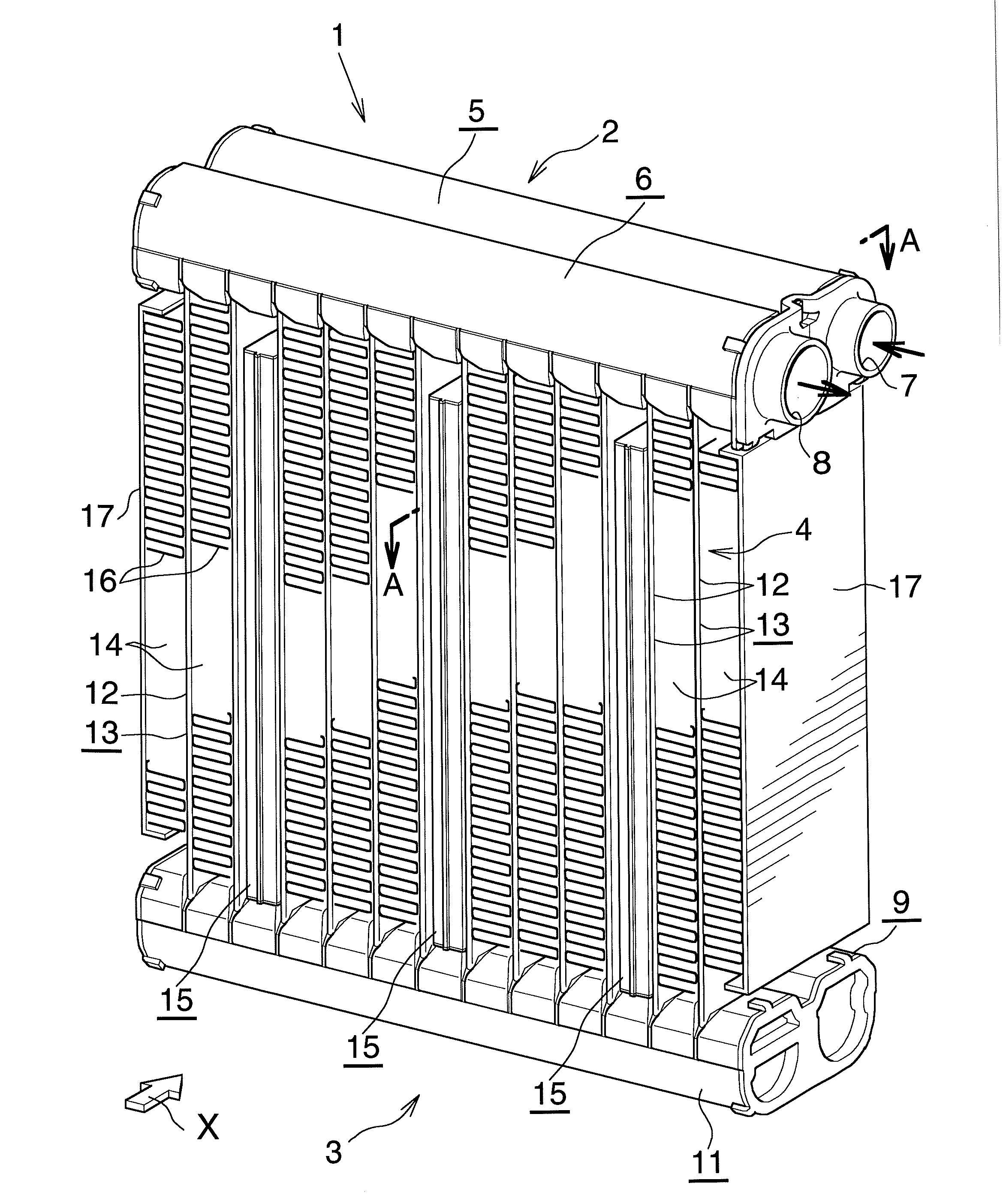
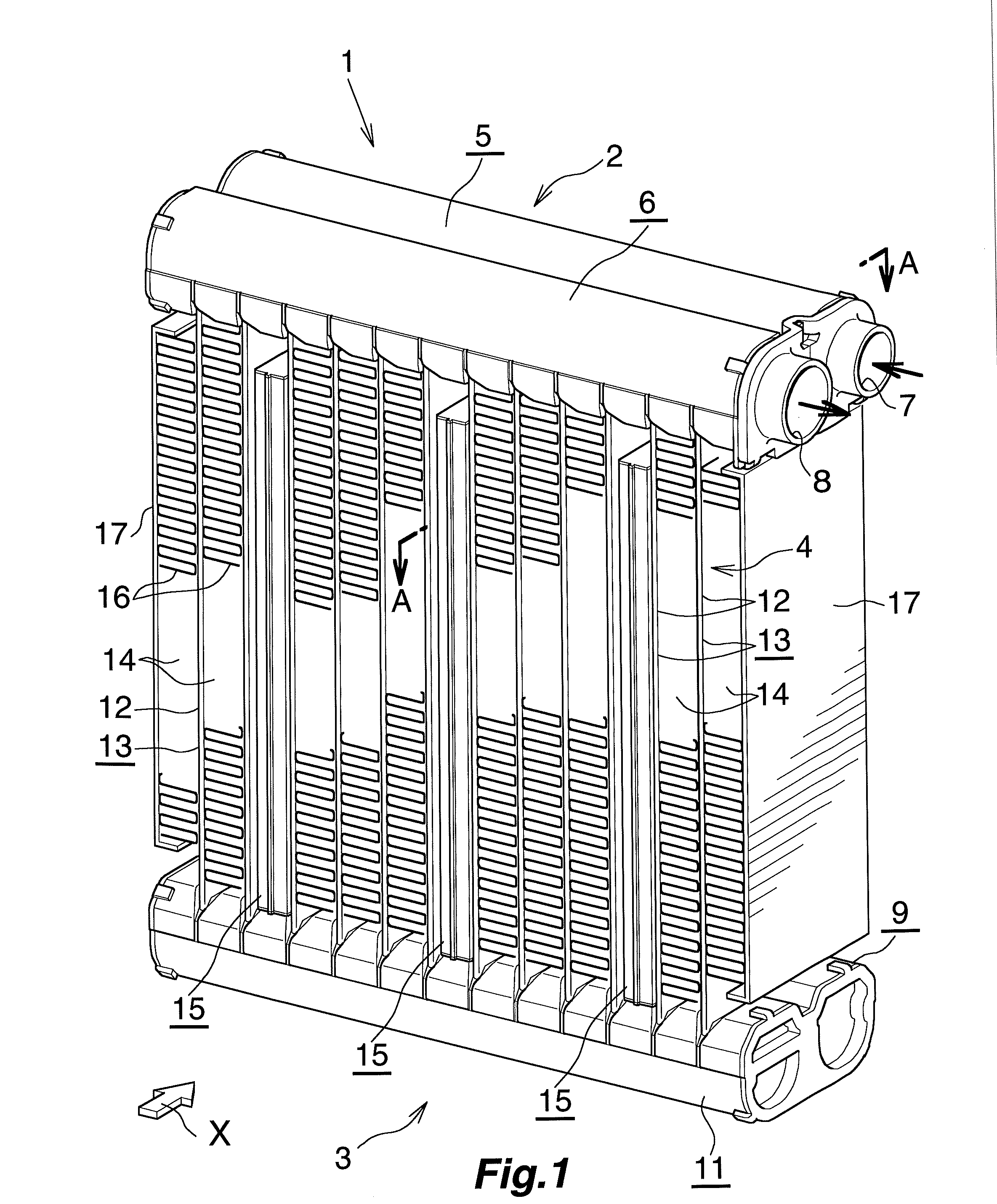
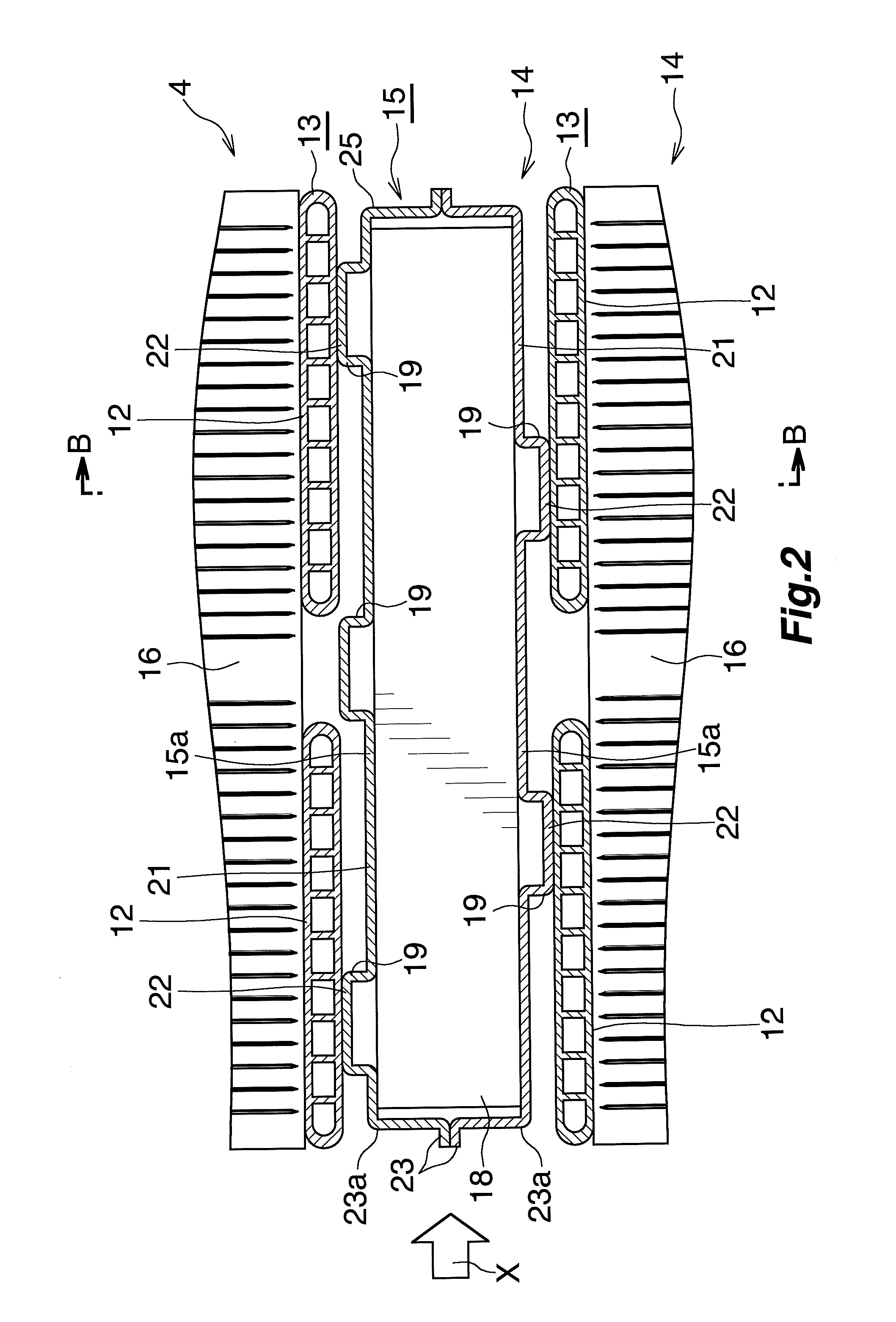
[0047]FIG. 1 shows the overall configuration of an evaporator with a cool storage function according to the present invention, and FIGS. 2 to 5 show the configuration of an essential portion of the evaporator.

[0048]As shown in FIG. 1, an evaporator with a cool storage function 1 includes a first header tank 2 and a second header tank 3 formed of aluminum and disposed apart from each other in the vertical direction such that they extend in the left-right direction; and a heat exchange core section 4 provided between the two ...


PUM


Abstract

An evaporator with a cool storage function includes flat refrigerant flow tubes, a cool storage material container disposed in at least one of all air-passing clearances each formed between adjacent refrigerant flow tubes, and an inner fin disposed in the cool storage material container. Each of left and right side walls of the cool storage material container has a contact portion in contact with the inner fin and a noncontact portion not in contact with the inner fin. In an overlap region where the left and right side walls of the cool storage material container overlap with the corresponding refrigerant flow tubes when the container is viewed from the left side or right side thereof, the area of the contact portion of each of the left and right side walls is greater than the area of the noncontact portion of each of the left and right side walls.

Description

BACKGROUND OF THE INVENTION[0001]The present invention relates to an evaporator with a cool storage function for use in a car air conditioner for a vehicle in which an engine serving as a drive source for a compressor is temporarily stopped when the vehicle is stopped.[0002]In the present specification and appended claims, the upper, lower, left-hand, and right-hand sides of FIGS. 1, 3, and 8 will be referred to as “upper,”“lower,”“left, and “right,” respectively.[0003]In recent years, in order to protect the environment and improve fuel consumption of automobiles, there has been proposed an automobile designed to automatically stop the engine when the automobile stops, for example, so as to wait for a traffic light to change.[0004]However, an ordinary car air conditioner has a problem in that, when an engine of an automobile in which the air conditioner is mounted is stopped, a compressor driven by the engine is stopped, and supply of refrigerant to an evaporator stops, whereby the...

Claims


Application Information

Patent Timeline
Patent Type & Authority Applications(United States)
IPC IPC(8): F25B39/02
CPCF25B39/02F25B2400/24B60H1/005Y02E60/145F28D20/02B60H1/00335F28D1/05391Y02E60/14
Inventor KAMOSHIDA, OSAMUHIGASHIYAMA, NAOHISA
Owner MAHLE INT GMBH
Why Eureka
Try Eureka