Hand Machine Tool

Active Publication Date: 2013-02-28
HILTI AG
View PDF27 Cites 7 Cited by
  • Summary
  • Abstract
  • Description
  • Claims
  • Application Information

AI Technical Summary

Benefits of technology

[0004]In some embodiments, the spring keeps the two clutch disks engaged by default. The stop maintains a distance between the second clutch disk and the first clutch disk. Consequently, the engagement depth of the second clutch disk with the first clutch disk is limited by the stop. If a torque applied to the sliding clutch exceeds a critical limit, the second clutch disk is deflected alongside the axis against the effect of the spring to the point where the two clutch disks are fully disengaged and the torque transmission is interrupted. The limiting value can be set with the engagement depth, which is defined by the relative position of the first clutch disk compared to the stop. As a result, the controlling unit enables the user to set a desired triggering torque.
[0005]According to one embodiment, the first clutch disk has cams and the second clutch disk has cams. The clutch disks are engaged with each other via the cams. Each of the cams of at least one of the two clutch disks has a convexly curved top, wherein the radius of curvature of the top increases toward the summit. The cam has a con

Problems solved by technology

Although the grooves can be disadvantageous for other models of a sliding clutch due to their larger

Method used


Image

  • Hand Machine Tool
  • Hand Machine Tool
  • Hand Machine Tool

Examples


Embodiment Construction

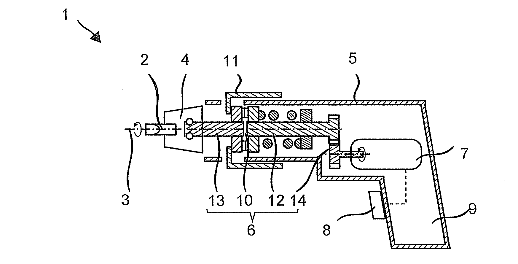
[0016]FIG. 1 illustrates an exemplary electric screw driver 1 which drives a tool 2, or example, a screw bit, around a working axis 3 in a rotary motion when in operation. A tool retainer 4 for a tool 2 is arranged on a case 5 and is pivotal around the working axis 3. The tool retainer 4 is coupled with an electric motor 7 via a drivetrain 6. The electric motor rotates in response to the operation of a system button 8. A user can start the electric screw driver 1 by means of the system button 8 and guide it by means of a handle 9 provided on the case 5.

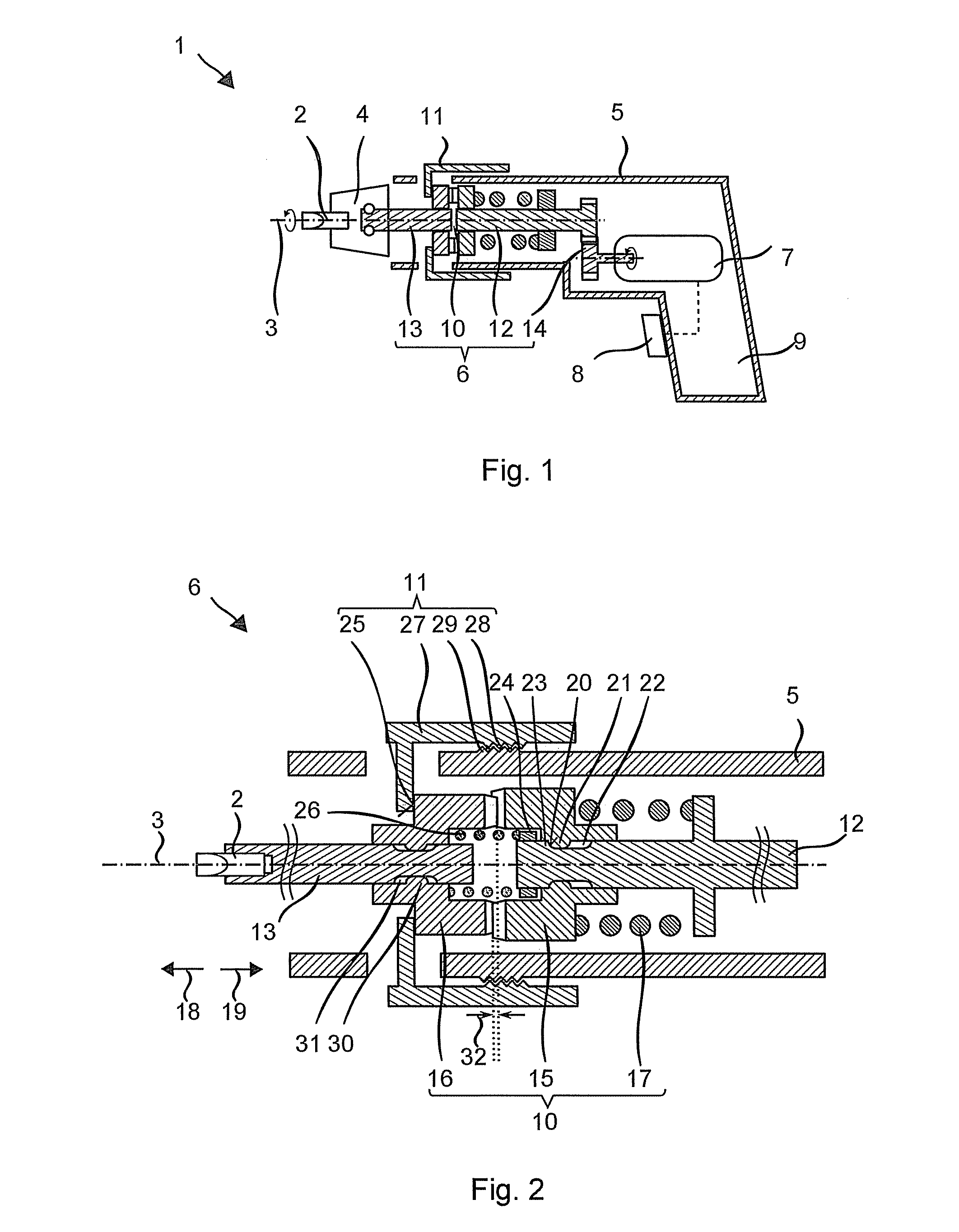
[0017]FIG. 2 illustrates a design of the drivetrain 6 with an adjustable sliding clutch 10, which interrupts a transmission of a torque if an applied torque exceeds a limiting value. The limiting values can be set by a user by means of a slide 11. The sliding clutch 10 engages with a countershaft 12 on the side of the drivetrain and with an output spindle 13 on the output side, which are both coaxial to the working axis 3. The counter...


PUM


Abstract

A hand machine tool includes a tool retainer that retains a tool, a motor that drives the tool retainer in a rotary motion, and a torque-controlled sliding clutch that is connected in a drivetrain between the motor and the tool retainer. The sliding clutch includes a first clutch disk, a second clutch disk, a spring and a controlling unit which can be activated manually. The second clutch disk is arranged displaceably alongside an axis limited by a stop in the direction toward the first clutch disk. Force is applied to the second clutch disk by the spring alongside the axis in the direction toward the first clutch disk. The manually activated controlling unit variably sets an axial distance between the first clutch disk and the stop, with which an engagement depth of the first clutch disk with the second clutch disk can be defined.

Description

CROSS-REFERENCE TO RELATED APPLICATIONS[0001]The present application claims priority to German Patent Application No. DE 10 2011 080 800.0, filed Aug. 11, 2011, which is hereby incorporated by reference herein in its entirety.FIELD OF THE INVENTION[0002]Some embodiments of the present invention relate to a hand machine tool and, in particular, to an electric screw driver.BRIEF SUMMARY OF THE INVENTION[0003]The hand machine tool according to some embodiments includes a tool retainer that retains a tool, a motor that drives the tool retainer in a rotary motion, and a torque-controlled sliding clutch that is connected in a drivetrain between the motor and the tool retainer. The sliding clutch includes a first clutch disk, a second clutch disk, a spring, and a controlling unit which can be activated manually. The second clutch disk is displaceably arranged alongside an axis limited by a stop in a direction toward the first clutch disk. Force is applied to the second clutch disk by the s...

Claims


Application Information

Patent Timeline
IPC IPC(8): F16D43/20
CPCB25B23/141B25B21/00
Inventor KELLER, VALENTINLUDWIG, MANFREDBAXIVANELIS, KONSTANTINWEBER, MICHAELROLL, BASTIAN
Owner HILTI AG
Why Eureka
Try Eureka