
Electrical on-board network and method for operating an electrical on-board network

a technology of electric on-board network and electrical network, which is applied in the direction of motor/generator/converter stopper, dynamo-electric converter control, capacitor propulsion, etc., can solve the problem of reducing the co2 emission of the drive, the possibility of saving energy through recuperation of braking energy, and the comparatively high cost of the on-board network, etc. problem, to achieve the effect of comparatively low cost, increase starting torque, and high degree of hybridization

Inactive Publication Date: 2013-02-28
ROBERT BOSCH GMBH +1
View PDF8 Cites 8 Cited by
  • Summary
  • Abstract
  • Description
  • Claims
  • Application Information

AI Technical Summary

Benefits of technology

The present invention is an electrical on-board system that allows for a high degree of hybridization and is cost-effective. It achieves this by using at least two phase systems, each connected to an inverter, and by connecting at least one phase system to each power circuit. The inverters can operate independently, allowing for a flexible energy distribution to the power circuits. A switching device is provided to connect or interrupt the connections between the phase systems and the power circuits, allowing for a plurality of configurations. The invention enables optimal exploitation of energy during braking and starting of the drive aggregate or internal combustion engine. Energy storage devices can be used selectively for starting and powering the drive aggregate.

Problems solved by technology

This has the disadvantage that it has only a limited maximum charge current or discharge current, which in addition is still a function of its state of charge.
Thus, the possibility of saving energy through recuperation of braking energy, and thus reducing the CO2 emission of the drive, is significantly limited.
The disadvantage of such an electrical on-board network is however its comparatively high cost outlay.
However, a disadvantage of this is that a higher loss of the electrical machine may occur.
Thus, it is not provided to separate the phase system from the power circuit.

Method used


Image

  • Electrical on-board network and method for operating an electrical on-board network
  • Electrical on-board network and method for operating an electrical on-board network
  • Electrical on-board network and method for operating an electrical on-board network

Examples


Embodiment Construction

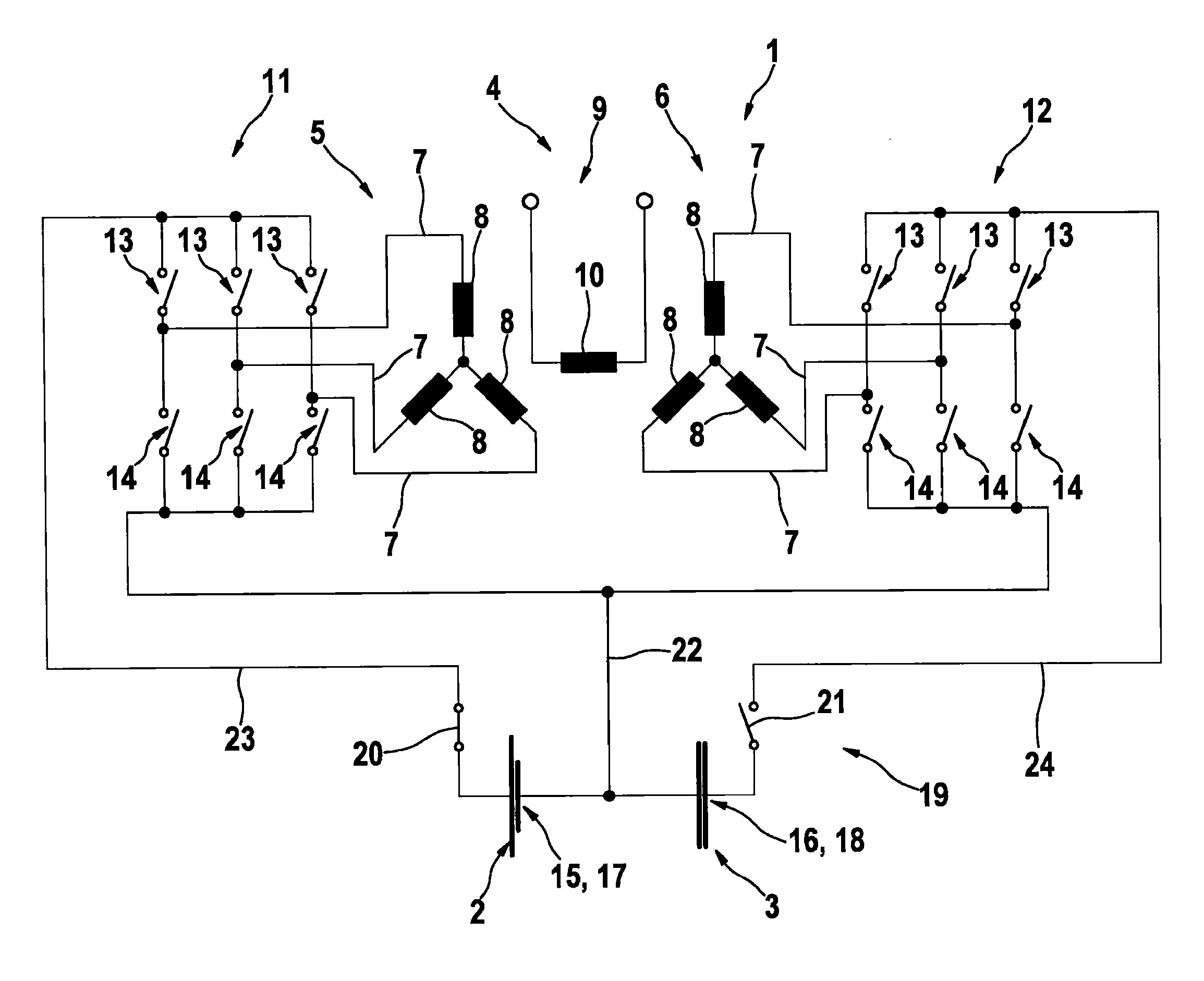
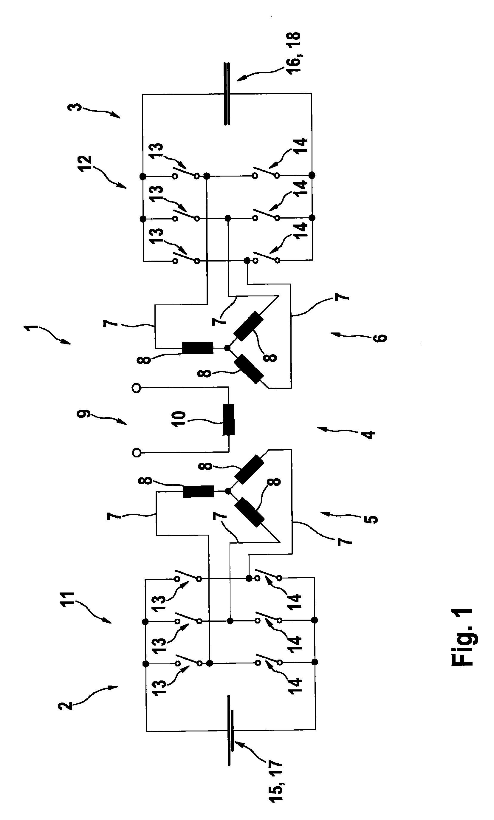
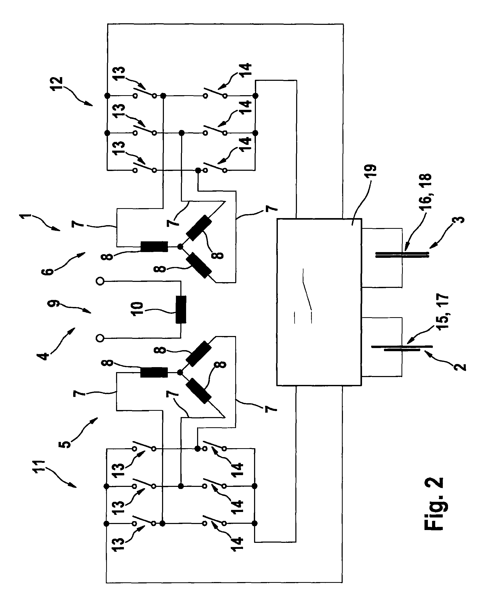
[0025]FIG. 1 shows a part of an electrical on-board network 1 of a vehicle (not shown in more detail). On-board network 1 has two power circuits 2 and 3 and an electrical machine 4 allocated to a drive of the vehicle. Power circuit 2 is for example a 12V power circuit and power circuit 3 is a 48V power circuit. In the specific embodiment of on-board network 1 shown here, electrical machine 4 is realized in a six-phase configuration, two phase systems 5 and 6 being provided each having three external conductors 7 of electrical machine 4. Each external conductor 7 is connected to a coil 8 or winding, allocated thereto, of electrical machine 4. The six phases of electrical machine 4 are thus divided into two groups each having three phases. Electrical machine 4 also has an exciter circuit 9 that is allocated to phase systems 5 and 6 and that has a coil 10. An excitation of electrical machine 4 is adjustable using exciter circuit 9.

[0026]Each of phase systems 5 and 6 is connected to a r...


PUM


Abstract

An electrical on-board network of a vehicle, having at least two power circuits and an electrical machine allocated to a drive of the vehicle. The electrical machine has at least two phase systems, connected to a respective inverter, and that at least one of the phase systems is capable of being electrically connected to at least one of the power circuits via the associated inverter. A method for operating an electrical on-board network of a vehicle is also described.

Description

FIELD OF THE INVENTION[0001]The present invention relates to an electrical on-board network of a vehicle, having at least two power circuits and having an electrical machine allocated to the drive of the vehicle. The present invention also relates to a method for operating an electrical on-board network of a vehicle.BACKGROUND INFORMATION[0002]Electrical on-board networks of the general type mentioned above are available. For example, European Patent No. EP 1 646 522 B1 describes a motor vehicle on-board network having a multi-voltage generator motor that includes an electrical machine, a regulator, and a pulse inverter. These are provided for the supply of electrical power to a first sub-network having at least one first consumer and to a second sub-network having at least one second consumer. In the first sub-network, a first nominal voltage should be present, and in the second sub-network a second nominal voltage should be present, and a DC / DC converter should be situated downstr...

Claims


Application Information

Patent Timeline
Patent Type & Authority Applications(United States)
IPC IPC(8): H02P25/22B60L50/16
CPCB60L7/14Y02T10/70B60L11/14B60L11/1855B60L15/007B60L2210/40B60R16/03Y02T10/7005Y02T10/7022Y02T10/705Y02T10/7077Y02T10/7241B60Y2400/112B60Y2400/114B60L11/005B60L50/40B60L50/16B60L58/19Y02T10/64Y02T10/72Y02T10/7072
Inventor KURFISS, JOCHENFINKE, SVEN
Owner ROBERT BOSCH GMBH
Learn More