Solid state power controller for high voltage direct current systems

Active Publication Date: 2013-02-28
HAMILTON SUNDSTRAND CORP
View PDF1 Cites 30 Cited by
  • Summary
  • Abstract
  • Description
  • Claims
  • Application Information

AI Technical Summary

Benefits of technology

[0011]FIG. 5 illustrates a flow chart for a DC lo

Problems solved by technology

However, switching devices within current SSPCs typically dissipate excessive heat at elevated current levels due to internal resistances,

Method used


Image

  • Solid state power controller for high voltage direct current systems
  • Solid state power controller for high voltage direct current systems
  • Solid state power controller for high voltage direct current systems

Examples


Embodiment Construction

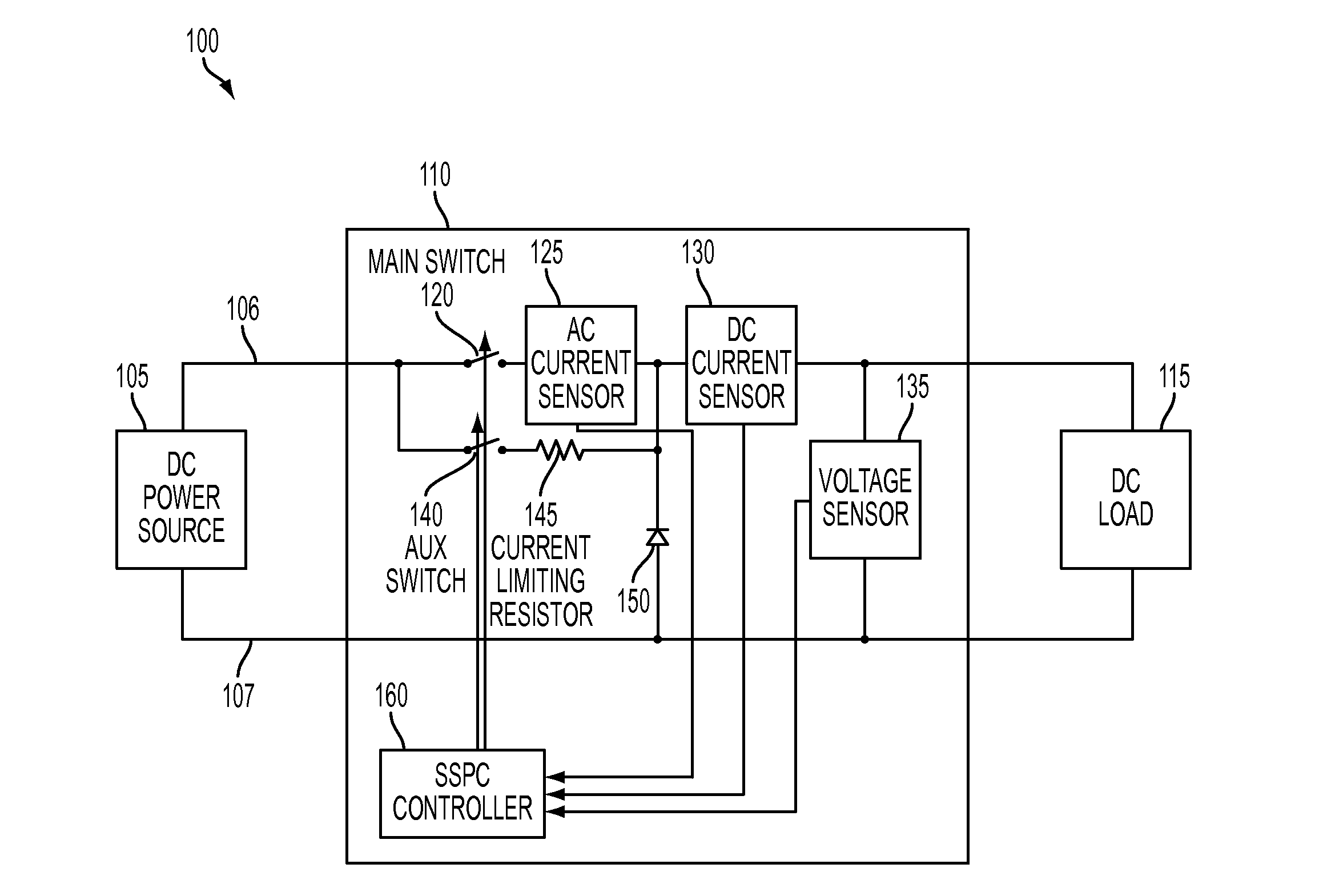
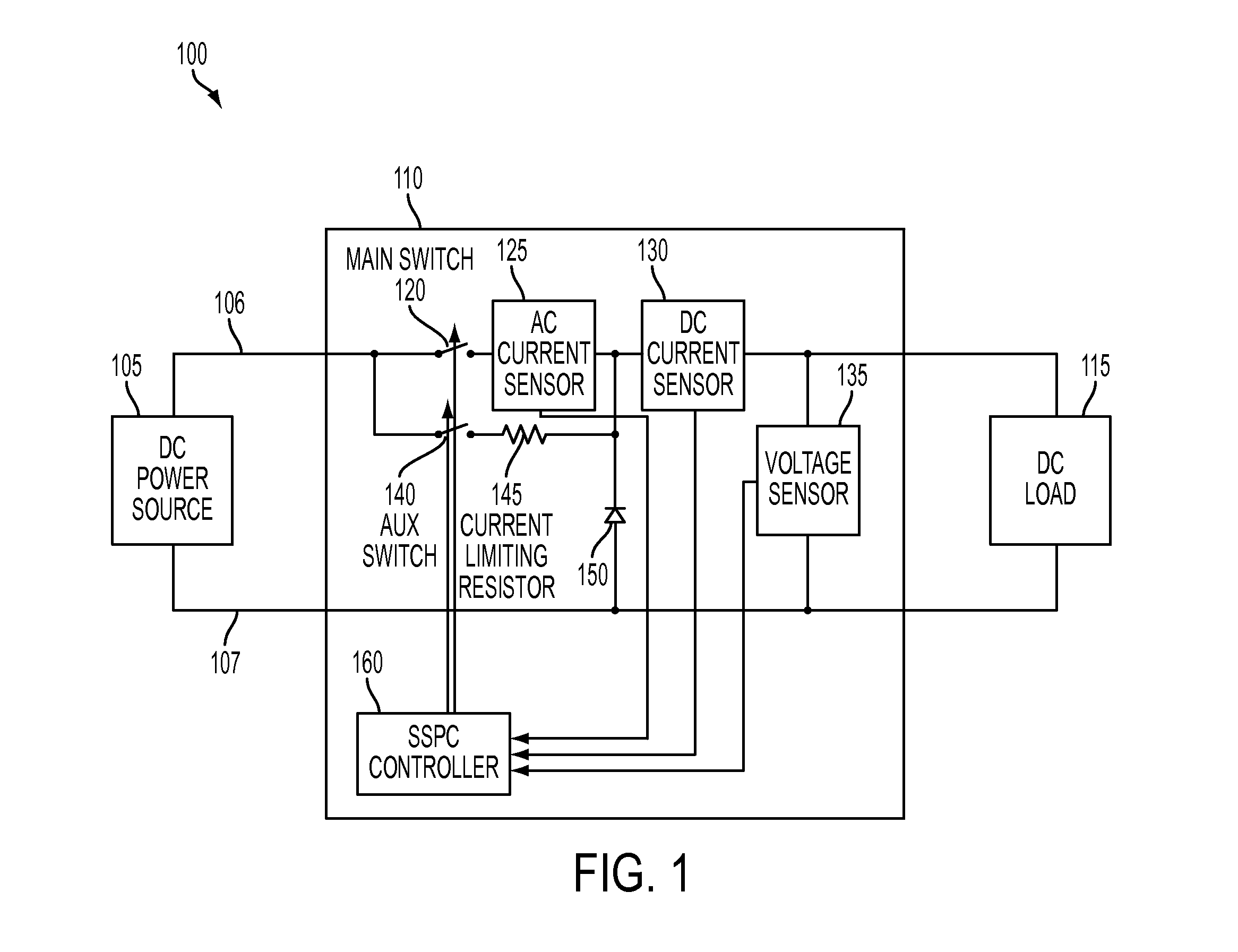
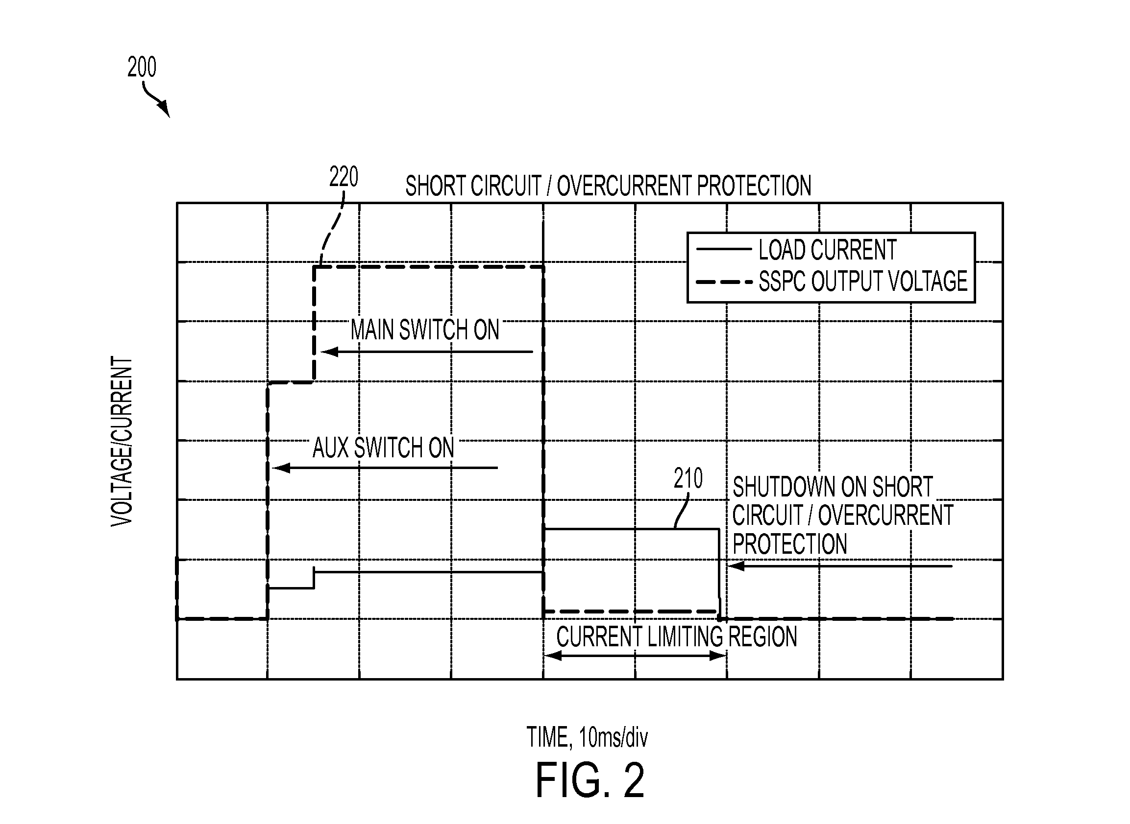
[0012]Exemplary embodiments include a SSPC in a DC power distribution system, enabling distribution and protection of DC loads, such as DC link motor controllers and export power inverters, or other types of DC loads. The architecture described herein utilizes an SSPC with two solid state circuit breakers coupled to current and voltage sensors. The main switch utilizes a high bandwidth alternating current (AC) current sensor to detect over current condition. Once the over current condition is detected, the main switch is turned-off and load current is limited by the auxiliary switch via current limiting resistor. If the load current measured by the DC current sensor is above threshold level for pre-determined period of time, the auxiliary switch is turned off and short circuit / overcurrent condition is announced by the protective function. FIG. 1 illustrates an SSPC high voltage DC system 100. As described herein, high voltage can be 600-800 VDC. The system 100 includes a DC power so...


PUM


Abstract

A solid state power controller system can include a direct current load, a solid state power controller apparatus including an alternating current sensor coupled to the direct current load, a direct current sensor coupled to the direct current load, a voltage sensor coupled to the direct current load, a main switch coupled to the direct current load via the alternating and direct current sensors, an auxiliary switch coupled in parallel to the main switch, a current limiting resistor coupled in series to the auxiliary switch and a solid state power controller coupled to the main switch, the auxiliary switch, the alternating current sensor, the direct current sensor, and the voltage sensor, and a direct current power source coupled to the solid state power controller apparatus.

Description

BACKGROUND OF THE INVENTION[0001]The subject matter disclosed herein relates to electric power generation and distribution, and more particularly to a solid state power controller (SSPC) for high voltage direct current (DC) systems.[0002]Electrical power systems in hybrid vehicles, such as military hybrid vehicles, can include high voltage direct current power generation and distribution systems. SSPCs can be used in a power distribution system to replace traditional electromechanical circuit breakers. The main functions of the SSPCs can include power distribution and protection of power to different loads. In comparison to electromechanical devices, SSPCs provide fast response time, and eliminate arcing during turn-off transients and bouncing during turn-on transients. In addition, SSPCs do not suffer severe degradation during repeated fault isolation as compared with electromechanical devices. SSPCs facilitate advanced protection and diagnostics, and provide more efficient power d...

Claims


Application Information

Patent Timeline
IPC IPC(8): H02H7/00
CPCH02H3/025H02H3/093H02H3/087H02H3/027H02H9/001H01H33/596H03K17/167H03K17/082H03K17/12H01H47/002
Inventor ROZMAN, GREGORY I.MOSS, STEVEN J.
Owner HAMILTON SUNDSTRAND CORP
Why Eureka
Try Eureka