
Revisable orthopedic anchor and methods of use

a technology of orthopedic anchors and reversible screws, which is applied in the field of bone anchors for use in orthopedic surgery, can solve the problems of weakened or degraded trabecular bone, complicated and oftentimes invasive procedures, and prior art solutions, etc., and achieves less complicated implantation, greater pull-out resistance, and superior bone purchase

Active Publication Date: 2013-02-28
DEPUY SYNTHES PROD INC
View PDF20 Cites 22 Cited by
  • Summary
  • Abstract
  • Description
  • Claims
  • Application Information

AI Technical Summary

Benefits of technology

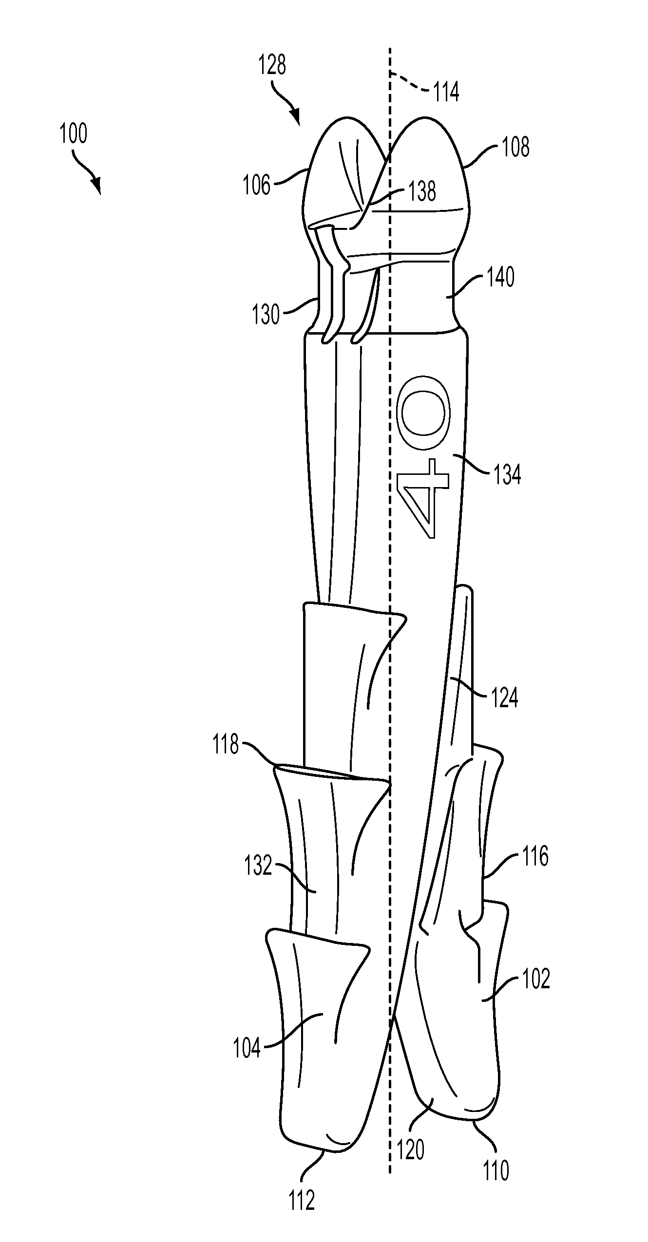
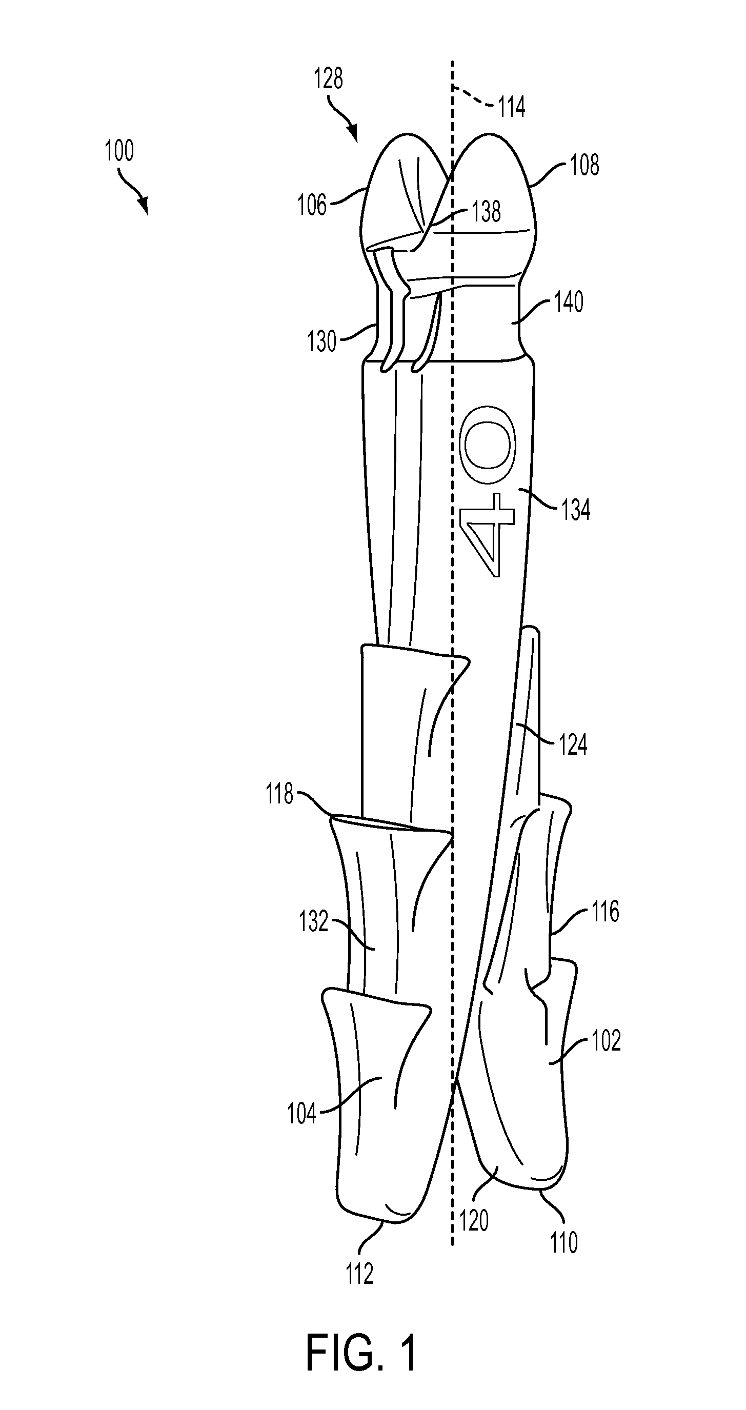
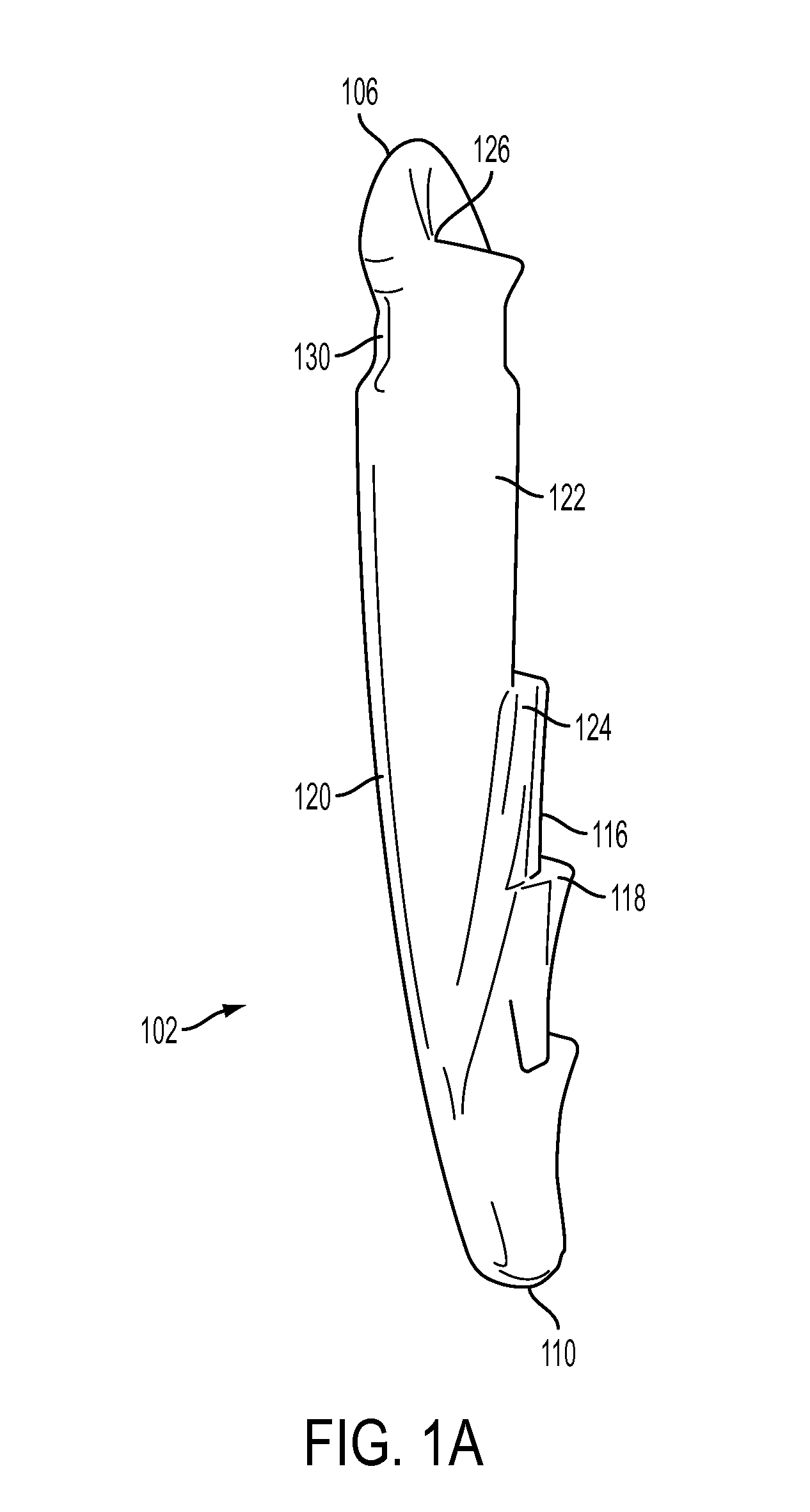
The present invention is a revisable orthopedic anchor that can be easily and securely implanted and removed from a patient's body. The anchor uses dual probes that have distal tips that diverge, allowing for better bone purchase. The probes can be separated and reversed during the implantation process. The anchor also includes a crimp head that keeps the probes in a fixed relationship with each other, preventing separation after implantation. The probe components can be made from a radiolucent material so they do not interfere with medical imaging technologies. The anchor has a unique design that results in resistance to removal.

Problems solved by technology

Degenerative conditions, which can result from diseases such as osteoporosis or injury, can cause the trabecular bone to weaken or degrade even further.
These prior art solutions, however, are not without potential drawbacks.
Accordingly, removal of these components requires a complicated and oftentimes invasive procedure.
This can be because radiolucent materials (e.g., any of various polymer-based materials) are often not suitable for creating fine features like threading on a screw.

Method used


Image

  • Revisable orthopedic anchor and methods of use
  • Revisable orthopedic anchor and methods of use
  • Revisable orthopedic anchor and methods of use

Examples


Embodiment Construction

[0054]Certain exemplary embodiments will now be described to provide an overall understanding of the principles of the devices and methods disclosed herein. One or more examples of these embodiments are illustrated in the accompanying drawings. Those skilled in the art will understand that the devices and methods specifically described herein and illustrated in the accompanying drawings are non-limiting exemplary embodiments and that the scope of the present invention is defined solely by the claims. The features illustrated or described in connection with one exemplary embodiment may be combined with the features of other embodiments. Such modifications and variations are intended to be included within the scope of the present invention.

[0055]In one aspect of the invention, a bone anchor is provided that includes two probe components configured to be assembled to form a complete bone anchor. Each probe component can be in the form of an elongate member having a proximal head and a ...


PUM


Abstract

A revisable orthopedic anchor and method of use for removably securing an anchor in bone, such as compromised or degenerated bone, is described herein. In one embodiment, the anchor makes use of dual probes and vector divergence of the distal tips of the probes to achieve superior bone purchase and pull-out resistance. In such an embodiment, the probes can be inserted one at a time into a hole formed in, for example, the pedicle bone. After the probes are inserted and joined at the proximal end, they have a greater pull-out resistance than a threaded anchor. Removing the anchor involves separating the proximal heads and reversing the implantation process. As a result of the unique bone anchor design disclosed herein, the devices and methods of the present invention allow for less complicated implantation and removal of orthopedic anchors, all while providing enhanced bone purchase when implanted in a patient.

Description

FIELD[0001]This invention is related to bone anchors for use in orthopedic surgery and, in particular, to devices and methods for implanting an anchor in bone such that the anchor provides enhanced bone purchase during use as well as easy removal.BACKGROUND[0002]Bone in human and other mammal bodies is generally classified into two types, cortical bone, also known as compact bone, and trabecular bone, also known as cancellous or spongy bone. Cortical bone is much denser than trabecular bone with a porosity ranging between 5% and 10%. Cortical bone is found primarily in the shaft of long bones and forms the outer shell around trabecular bone at the end of joints and the vertebrae.[0003]In the vertebrae, each bone is generally heart shaped, with spinous, inferior and superior processes joined to the vertebral body via opposing pedicles. To stabilize or fix deformities in the spine, implantable medical devices, known as spinal fixation devices, can be employed between adjacent vertebra...

Claims


Application Information

Patent Timeline
Patent Type & Authority Applications(United States)
IPC IPC(8): A61B17/70A61B17/84
CPCA61B17/0401A61F2310/00023A61B17/7037A61B17/7049A61B17/7076A61B17/8685A61B2017/0414A61B17/844A61B2017/8655A61F2/30965A61F2/447A61F2/4611A61F2002/2817A61F2002/2835A61F2002/30509A61F2002/30607A61F2002/30616A61F2002/30779A61F2002/30787A61F2002/30828A61F2002/30843A61F2002/4475A61B17/7001A61F2002/30507A61F2002/30593
Inventor HAWKINS, JOHN RILEYGRINBERG, ALEXANDERMICHIELLI, MICHAEL
Owner DEPUY SYNTHES PROD INC
Learn More