
Air separation plant control

Active Publication Date: 2013-02-28
PRAXAIR TECH INC
View PDF1 Cites 5 Cited by
  • Summary
  • Abstract
  • Description
  • Claims
  • Application Information

AI Technical Summary

Benefits of technology

The patent describes a computer program that can accurately calculate the oxygen concentration of different streams in an air separation plant. This is done by using models that are continuously adjusted to minimize the differences between the calculated and measured oxygen concentrations. This will ensure that the program's calculations are accurate for the controlled variables in the process.

Problems solved by technology

A disadvantage of such a control scheme is that a change in reflux to the lower pressure column will not instantaneously change the nitrogen content in the crude argon feed stream.
The problem with this type of control is that once nitrogen is seen at critical concentrations in the argon product, it is often too late to take effective control action to prevent the argon column from shutting down with a loss of argon production.

Method used


Image

  • Air separation plant control
  • Air separation plant control
  • Air separation plant control

Examples


Embodiment Construction

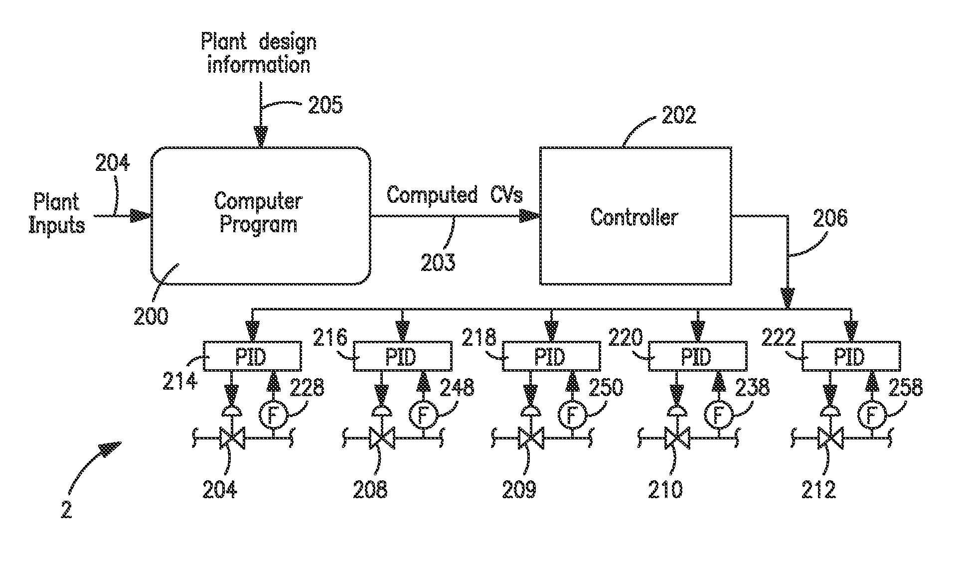
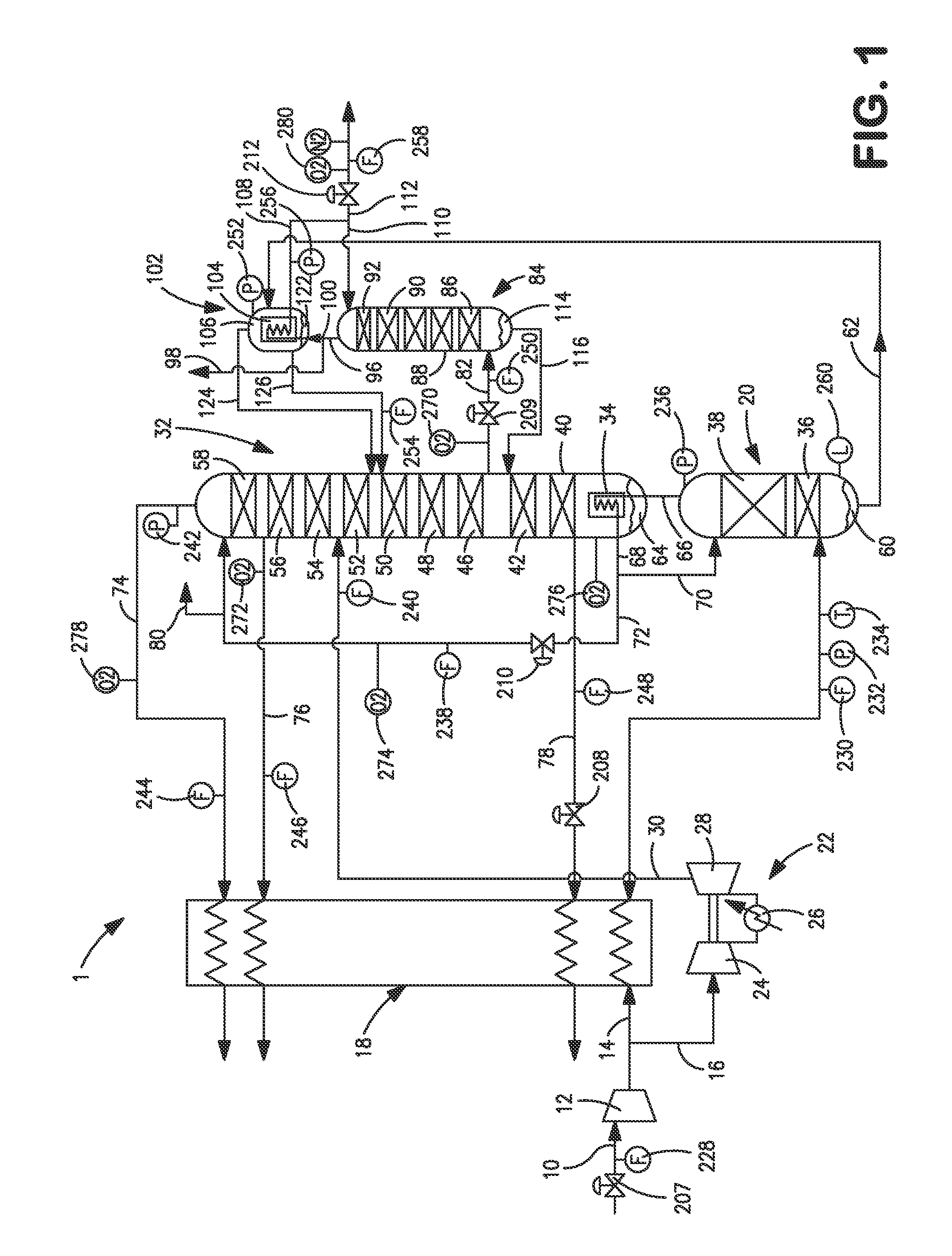
[0026]With reference to FIG. 1, an air separation plant 1 is illustrated that is designed to produce an argon product which is discharged from air separation plant 1 as an argon product stream 112. Argon product stream 112 would typically have a purity of about 98 percent and as such, would be a crude argon product in which oxygen and nitrogen would have to be removed by downstream process known in the art. It is understood, however, that air separation plant 1 is illustrated for exemplary purposes only and the present invention is therefore not limited to the illustrated plant. For example, air separation plant 1 could be designed to produce an argon product having oxygen and nitrogen impurities less than 2 ppm. In such case the argon column would be formed of two columns collectively having sufficient stages of separation to produce such a product. The control system of the present invention is not illustrated in FIG. 1 so that the operation of the illustrated air separation plant...


PUM


Abstract

A method of controlling an air separation plant and a control system to optimize production of an argon product produced by the plant. A computer program is continually executed that has models of each column of the plant, a condenser reboiler and an argon reflux condenser. The models contain stage models of each stage of separation within each of the columns that when assembled are able to calculate current values of controlled variables in response to input variables applied to the models. The controlled variables serve as an input to a controller that controls manipulated variables comprising flow rates of an air feed stream to the air separation plant, a product oxygen stream removed from the lower pressure column and the crude argon feed stream such that the controlled variables are within a targeted range selected to optimize the production of the argon product.

Description

FIELD OF THE INVENTION [0001]The present invention relates to a method and control system for controlling an air separation plant to maximize production of an argon product. More particularly, the present invention provides such a method and system in which flow rates of the air fed to the distillation columns of the plant, the product oxygen and a crude argon feed stream are controlled such that estimated concentrations of the argon concentration in a waste nitrogen stream and a nitrogen concentration within a crude argon feed stream fed to an argon column are within targeted ranges that will maximize production of the argon product.BACKGROUND OF THE INVENTION[0002]Argon products are produced by separating the argon from air through the use of cryogenic rectification that is conducted within an air separation plant. The argon produced can be a crude argon product that is generally further processed to remove oxygen and nitrogen or a purified argon product containing very little oxy...

Claims


Application Information

Patent Timeline
IPC IPC(8): G05B15/02
CPCF25J3/04848F25J3/04303G05B13/048F25J3/04678F25J2290/10F25J3/04412
Inventor SINGHAL, ASHISHBLOUIN, STEPHANE
Owner PRAXAIR TECH INC
Learn More