Fuel supply device of gas turbine engine

a gas turbine engine and fuel supply technology, which is applied in the direction of machines/engines, valve operating means/release devices, lighting and heating apparatus, etc., can solve the problems of increasing the amount of no/sub>x in the exhaust gas, degrading combustion stability, and very low combustion concentration in the combustion zone, so as to achieve sufficient fuel sealing performance and simple and inexpensive structure

Active Publication Date: 2013-03-07
KAWASAKI HEAVY IND LTD
View PDF3 Cites 10 Cited by
  • Summary
  • Abstract
  • Description
  • Claims
  • Application Information

AI Technical Summary

Benefits of technology

[0014]A fuel supply device of a gas turbine engine of the present invention has a s

Problems solved by technology

With an increase in the temperature of the air at the inlet of the fuel supply device, a combustion temperature rises, which may undesirably result in an increase in the amount of NOx in the exhaust gas.
However, in the lean pre-mixed combustion method, since a great amount of air and fuel are mixed uniformly, a local combustion concentration in a combustion zone is very low, which degrades combustion stability particularly under a low load state.
However, if the flow control valves are provided in these two fuel passages, respectively, a ratio of the weight and cost of the flow control valves and the controller with respect to weight a

Method used


Image

  • Fuel supply device of gas turbine engine
  • Fuel supply device of gas turbine engine
  • Fuel supply device of gas turbine engine

Examples


embodiment 1

[0028]First of all, Embodiment 1 of the present invention will be described with reference to FIGS. 1 to 7. Hereinafter, description will be given sequentially of the configuration of a combustor, the configuration of a fuel control system, the configuration of a fuel divider, the operation of the fuel divider, and the relation between a fuel pressure and a flow (flow rate) of the fuel.

[0029]

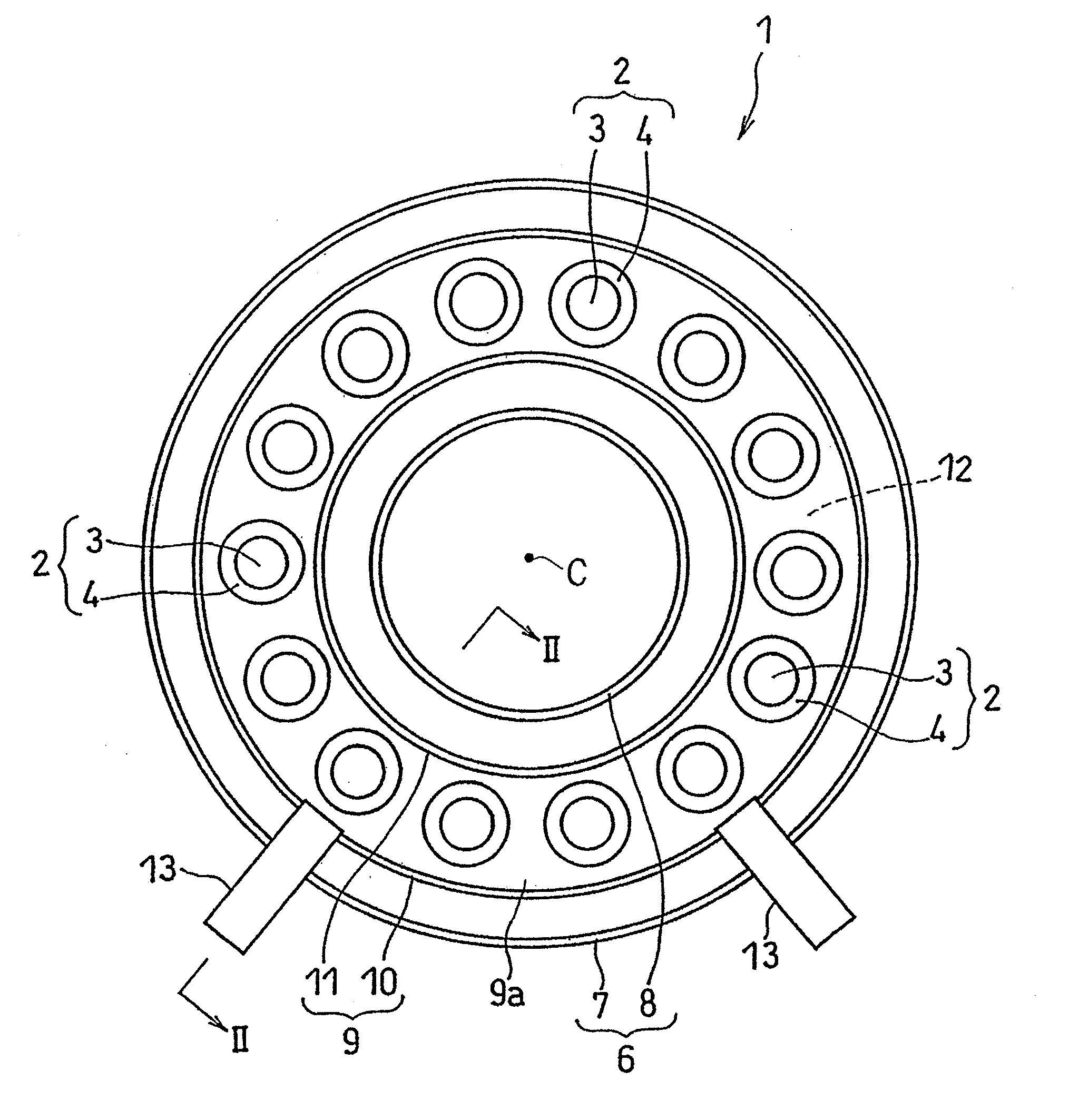
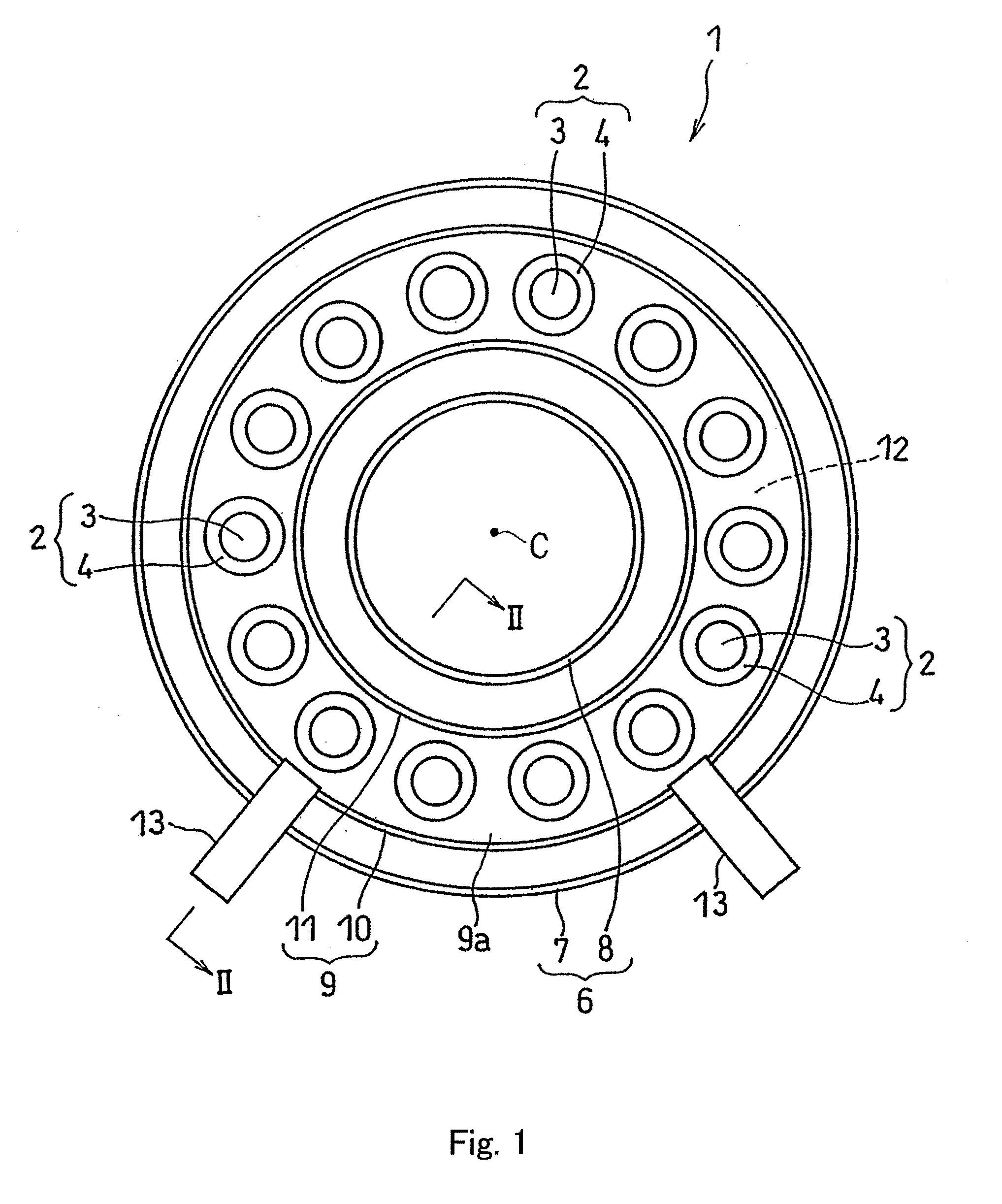
[0030]FIG. 1 shows a head portion of a combustor 1 of a gas turbine engine including a fuel supply device according to Embodiment 1 of the present invention. The combustor 1 is configured to combust an air-fuel mixture generated by mixing fuel with compressed air supplied from a compressor (not shown) in the gas turbine engine, and feed high-temperature and high-pressure combustion gas generated by the combustion to a turbine to drive the turbine.

[0031]The combustor 1 is of an annular type and has a configuration in which a tubular inner casing 8 is disposed inward relative to a tubular outer ca...

embodiment 2

[0064]Subsequently, a fuel supply device of Embodiment 2 of the present invention will be described with reference to FIGS. 8 to 10. The fuel supply device of the present embodiment is basically identical in configuration to the fuel supply device of Embodiment 1, except for the configuration of the fuel divider. Therefore, hereinafter, a fuel divider 66A of the present embodiment will be described in a larger part.

[0065]

[0066]First of all, the configuration of the fuel divider 66A will be described. FIG. 8 is a longitudinal sectional view showing the fuel divider 66A of Embodiment 2. As shown in FIG. 8, the fuel divider 66A of the present embodiment includes a housing unit 201, a drive element 203, a pilot port needle valve element 211, and a main port needle valve element 212. These components will be described sequentially.

[0067]The housing unit 201 is a member for housing the drive element 203 therein. As shown in FIG. 8, the housing unit 201 is provided on a top portion thereof...

embodiment 3

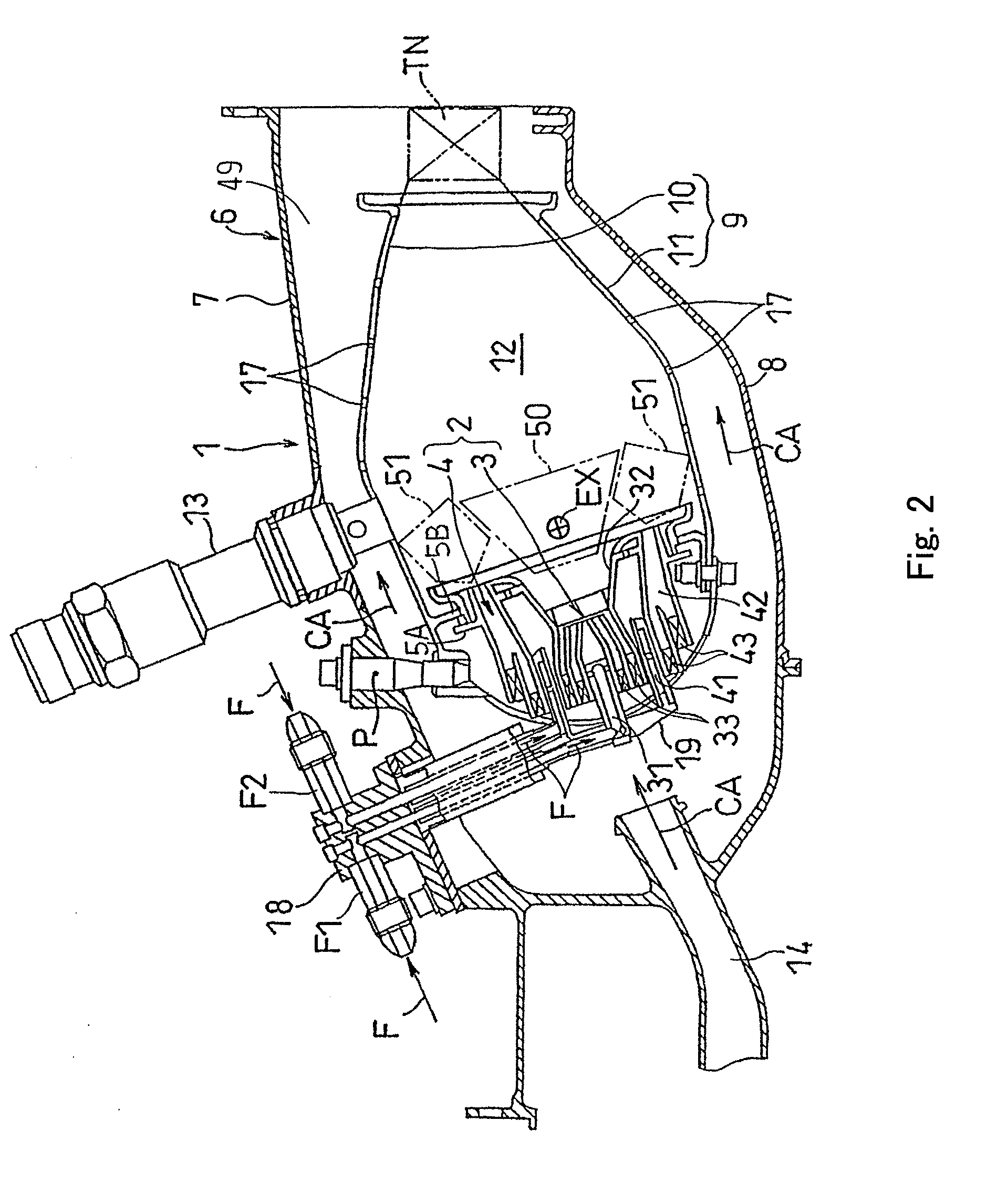
[0079]FIG. 11 is a view showing a fuel control system according to Embodiment 3 of the present invention. In the present embodiment, the collecting fuel passage 63 is extended up to the fuel injection units 2, and the fuel divider 66 is provided for each of the fuel injection units 2 in a one-to-one correspondence. This follows that the pilot fuel passage 64 and the main fuel passage 65 are provided independently for each of the fuel injection units 2. As shown in FIG. 12, the fuel divider 66 is built into, for example, the fuel pipe unit 18 of each of the fuel injection units 2. In this configuration, the single collecting fuel passage 63 with a great cross-section is sufficient to reach each of the fuel injection units 2. This makes it easier to perform a piping work for laying out the fuel passage to the fuel injection units 2 as compared to the configuration in which two fuel passages, i.e., the pilot fuel passage 64 and the main fuel passage 65 are used, like Embodiment 1. The ...


PUM


Abstract

In a fuel supply device of a gas turbine engine of the present invention, a fuel divider 66 includes a fuel entrance E1 into which the fuel supplied from a collecting fuel passage 63 is introduced; a pilot port 76 connected to the pilot fuel passage 64; a main port 77 connected to the main fuel passage 65; a pilot port needle valve element 101 which adjusts an opening degree of the pilot port 76; a main port needle valve element 102 which opens and closes the main port 77; and a drive element 100 which is actuated according to the fuel pressure at the fuel inlet E1 to drive the pilot port needle valve element 101 and the main port needle valve element 102.

Description

TECHNICAL FIELD[0001]The present invention relates to a fuel supply device of a gas turbine engine for supplying a fuel to a combustor including pilot burners and main burners.BACKGROUND ART[0002]For environment protection purposes, in gas turbine engines, strict environmental standards are set in a composition of combustion exhaust gas emitted. It is required to reduce harmful substances such as nitrogen oxide (hereinafter expressed as NOx) from the exhaust gas. In large-sized gas turbines and engines for aircraft, a pressure ratio tends to be set high, because of requirement of low fuel consumption and a high power output. Correspondingly, air at an inlet of a fuel supply device tends to be placed in higher temperature and higher pressure conditions. With an increase in the temperature of the air at the inlet of the fuel supply device, a combustion temperature rises, which may undesirably result in an increase in the amount of NOx in the exhaust gas.[0003]Under the circumstances, ...

Claims


Application Information

Patent Timeline
IPC IPC(8): F02C7/228
CPCF02C7/228F16K11/044F16K31/10F16K31/528Y02T50/672F23K5/06F23K5/147F23R3/343F23K5/04F05D2240/35F05D2220/323F05D2270/3015Y02T50/60
Inventor OGATA, HIDEKIOHYAMA, KAZUHIKOHATANO, TOMOYUKISHIMIZU, AKIHIROMIWA, TOUYA
Owner KAWASAKI HEAVY IND LTD
Why Eureka
Try Eureka