Handheld portable fundus imaging system and method

a portable, portable technology, applied in optics, medical science, instruments, etc., can solve the problems of increasing health problems, insufficient image quality, and inability to meet current requirements, and achieve the effect of reducing the number of portable systems, and increasing the number of health problems

Inactive Publication Date: 2013-03-07
MASIDAH CORP
View PDF3 Cites 70 Cited by
  • Summary
  • Abstract
  • Description
  • Claims
  • Application Information

AI Technical Summary

Benefits of technology

[0019]An object of the present invention is to mitigate the above-mentioned limitations or deficiencies of known fundus cameras, or at least provide an alternative.

Problems solved by technology

Various medical conditions, such as diabetes, macular degeneration, or glaucoma, are widespread and an increasing health issue, in both developed and developing countries.
However, available compact or portable systems do not address current requirements or do not provide sufficient image quality.
Typically, fundus cameras are intended for fixed installation, e.g. in a hospital or clinic, and thus tend to be large, bulky and heavy.
These cameras also tend to be expensive, several costing more than $50,000.
However, the basic device remains large and manoeuvrability is limited.
The cart is suitable for mobile use in a doctor's office or hospital setting, but not suitable for portable or mobile field use.
Its high cost has also been a severe limitation to its use in a number of hospitals and clinics.
Due to the presence of reflections, obtaining images can be challenging particularly in uncooperative patients or patients unable to place their head in a chin rest.
Such panning, unless done in a pre-determined sequence, can make interpretation of the findings difficult as landmarks within the eye are limited.
Use of baffles significantly reduces the field of view.
As mentioned in some of the above references, imaging of the eye presents particular challenges, that is, the eye itself is an optical system with its own lens and a highly reflective curved surface of the cornea, which tends to cause problems with reflections or glare when illuminating the eye.
Also, the small size of the aperture presented by an undilated pupil, and the need for a wide angle of view to image the curved surface of the fundus, requires a short working distance.
In compact handheld devices, limited space for optical components may necessitate changes to conventional optical systems in larger, bulkier conventional fundus cameras.
In practice, for example, in attempting to shorten the optical path for compact systems, it is found that annular or ring illumination systems lead to problems with reflections, and poor image quality.
Within the camera, reflections can be reduced to some extent by suitable optical coatings on lenses or reflectors, but these coatings tend to be a very expensive part of the optics, and add considerably to the cost of the optical system.
However, in practice, existing portable systems have been found to have inconveniently short battery life.

Method used


Image

  • Handheld portable fundus imaging system and method
  • Handheld portable fundus imaging system and method
  • Handheld portable fundus imaging system and method

Examples


first embodiment

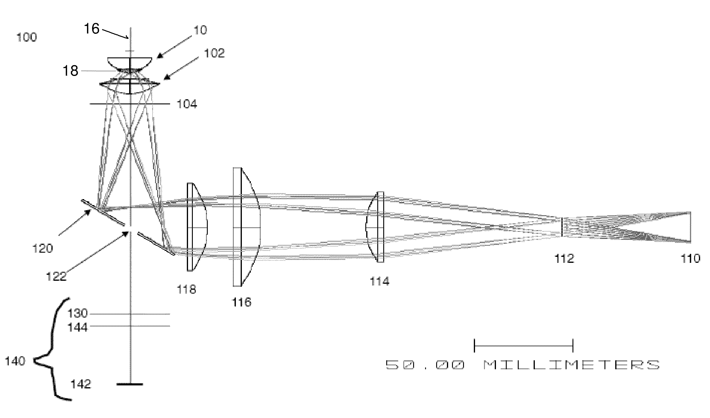
[0058]Optical elements of a fundus imaging system 200 according to the present invention are shown schematically in FIG. 10. This system 200 comprises an aspheric ophthalmic lens 202 for focusing light from an LED illuminator 210 into the eye 10 through the pupil 18 and lens 12 of the eye 10, to illuminate the fundus 16. The double aspheric lens 202 collects light reflected from the fundus 16, focusing it at the intermediate focus plane 204 of the aspheric lens 202, and light is directed through an achromatic lens 230 into the objective lens 244 of a camera imaging system 240, to image the fundus in the plane of the image sensor 242 of the camera. The LED illuminator 210 is placed at a position 212 along the optical axis of the system so as to produce, through the aspheric lens 202, a sharply focused image of the illumination source at the pupillary plane 218. An opaque occluder 250 is provided so as to occlude or block illumination to part of the field of view and selectively illum...

second embodiment

[0063]In a practical implementation, an optical system 300 for imaging of interior parts of an eye 10, according to the present invention, is illustrated schematically in FIG. 12. The system 300 comprises an assembly of a fundus imaging system adapter 301 and a conventional digital camera 340 having an off the shelf camera objective lens 344. The adapter 301 is enclosed in a housing 370 (not shown in FIG. 12) and is coupled to the camera objective via an achromatic lens 330. The other optical elements of the fundus imaging camera adapter comprise an aspherical ophthalmic lens 302, an LED illuminator 310, and a polarizer 360. A semicircular occluder 350 is mounted on a motorized mount 352, including a small motor 354 and drive system 356 to allow the semicircular occluder 350 to be rotated around the optical axis of the system. Referring to FIGS. 13 and 16, which show the arrangement of the LED illumination system 310, four individual light emitting diodes (LED) LED1, LED2, LED3 and ...


PUM


Abstract

A system and method for fundus imaging wherein selective illumination of a sector of the field of view of the fundus, using off-axis illumination, provides images of acceptable clarity, resolution, and size, with significantly reduced reflections, in a compact system. By rotating illumination around the optical axis, sectors of the fundus may be selectively and sequentially illuminated. An image of the entire field of view of the fundus is obtained by combining images, e.g. two or more half images, obtained within a single shutter exposure or capture period. An illumination system using LED light sources and a rotatable occluder provides for a lightweight, handheld and portable fundus imaging system. It may take the form of a fundus camera, a fundus imaging lens module for regular camera, or an adapter which couples to the standard lens of a camera to create a low cost fundus camera.

Description

CROSS-REFERENCE TO RELATED APPLICATIONS[0001]This application is a continuation-in-part of PCT International patent application no. PCT / CA2009 / 001183, filed 31 Aug. 2009, designating the United States, entitled “Handheld portable fundus imaging system and method”. This application also claims priority from U.S. Provisional application No. 61 / 447,256 filed Feb. 28, 2011, entitled “Handheld portable fundus imaging system and method”. Both applications are incorporated herein by reference in their entirety.BACKGROUND OF THE INVENTION[0002]1. Technical Field[0003]This invention relates to fundus imaging systems and methods for retinal imaging and screening, and particularly to portable or mobile fundus cameras and camera adapters, suitable for handheld use, to enable remote deployment e.g. in the field, areas without clinic facilities, or for telemedicine.[0004]2. Background Art[0005]A fundus camera, or retinal camera, is a specialized low power microscope with an attached imaging devic...

Claims


Application Information

Patent Timeline
Patent Type & Authority Applications(United States)
IPC IPC(8): A61B3/15G03B15/02
CPCG03B15/14A61B3/12
Inventor DE SMET, MARC
Owner MASIDAH CORP
Why Eureka
Try Eureka