Eureka AIR delivers breakthrough ideas for toughest innovation challenges, trusted by R&D personnel around the world.

Apparatus and Methods for Cell Culture

a cell culture and apparatus technology, applied in the field of apparatus for cell culture, can solve the problems of high cost, damage or kill all stem cells, and the culture of certain types of cells such as stem cells is much more delicate than the culture of cell lines, and achieves the desired quality level, good growth, and more cost-effective culture

Active Publication Date: 2013-03-07
PALL ARTELIS
View PDF8 Cites 14 Cited by
  • Summary
  • Abstract
  • Description
  • Claims
  • Application Information

AI Technical Summary

Benefits of technology

The present invention aims to provide a more affordable bioreactor for growing cells, particularly stem cells and primary cells, while allowing them to attach to a surface and grow in two dimensions. Additionally, it allows for the harvesting of cells with desired quality levels.

Problems solved by technology

Experiments have shown that the culture of certain types of cells such as stem cells is much more delicate than the culture of cell lines, due to several factors.
Typical procedures in use in the production of cell lines both to expand and to harvest cells out from a bioreactor are often not appropriate for stem cells; they easily damage or kill all the stem cells.
Such systems have the disadvantage of being highly inefficient in terms of the available surface per unit volume.

Method used


Image

  • Apparatus and Methods for Cell Culture
  • Apparatus and Methods for Cell Culture
  • Apparatus and Methods for Cell Culture

Examples


first embodiment

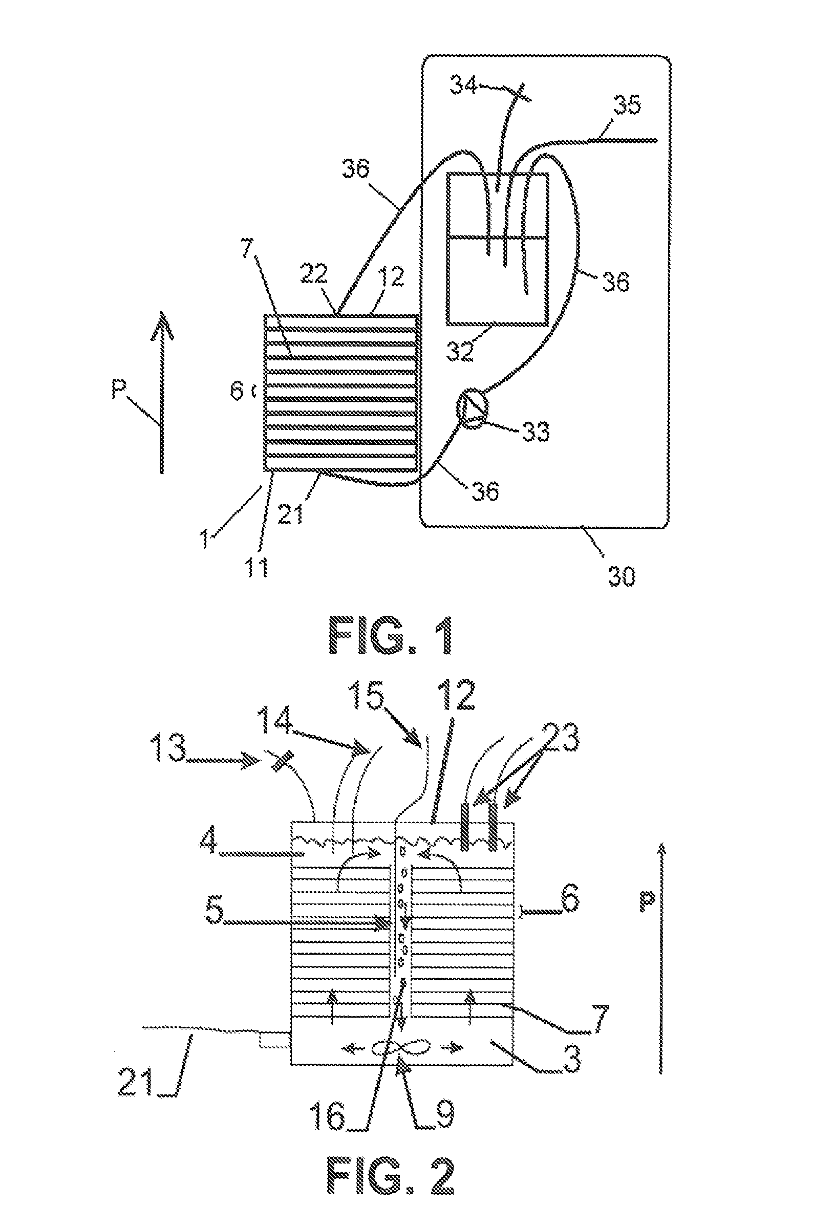
[0140]FIG. 1 shows a diagrammatical view of the bioreactor according to the invention. The bioreactor 1 is provided with a first side 11 and an opposite second side 12. A stack of carriers 7, which are preferably, is present in the bioreactor 1. The carriers are stacked along a principal direction P extending from the first side 11 to the second side 12. The carriers 7 are provided with open spaces (not shown). The bioreactor 1 of this embodiment is provided with an external circulation system 30. The external circulation system 30 comprises a medium storage tank 32 that is coupled to the bioreactor 1 through tubes 36. An external pump 33 is present for enabling flow of medium through the bioreactor 1. Medium flowing through the tubes enters the bioreactor 1 at inlet port 21 on the first side 11 of the bioreactor 1. It passes each carrier 7 within the bioreactor 1 through the open spaces therein, and then leaves the bioreactor at outlet port 22 on the second side 12 of the bioreacto...

second embodiment

[0141]FIG. 2 is a cross-sectional diagrammatical view of the bioreactor 1. The embodiment shown here is a bioreactor in which a circulation system is integrated. In this example the reactor is provided with a lower cavity 3, an upper cavity 4 and a fluid channel 5 extending between the lower and upper cavity 3, 4 along the principal direction P of the bioreactor 1. The fluid channel 5 is in the example shown here a columnar channel located in the center of the bioreactor 1, which is preferably of cylindrical shape. The carriers 7 are stacked along the same direction. The stacking occurs in one embodiment by means of mechanical connections defining the side wall of the columnar channel 5. These mechanical connections may fix the orientation of each carrier in the stack, but alternatively may leave freedom for independent rotation of each of the carriers. Clearly, it is by no means excluded that the stack of carriers including the columnar channel could be manufactured as one piece, f...


PUM

PropertyMeasurementUnit
diameteraaaaaaaaaa
distanceaaaaaaaaaa
widthaaaaaaaaaa

Abstract

A bioreactor (1) for the culture of cells (C) comprising a stack of carriers (7) for cell (C) adherence and liquid medium (M) distribution. The carriers (7) are stacked so as to define levels (6) between adjacent carriers (7) for the flow of the liquid medium (M). Adjacent levels (6) are fluidly interconnected via open spaces (2) so that the liquid medium (M) can flow from one level (6) to an adjacent level (6). The open spaces (2) between a first and an adjacent second level (6′) do not overlap with the one or more open spaces (2) between the second level (6′) and an adjacent third level (6″). One or more of the carriers may also include an area adapted to prevent cell adhesion or growth, thereby allowing for the viewing of cell growth on adjacent carriers from a vantage point external to the bioreactor. Related methods are also disclosed.

Description

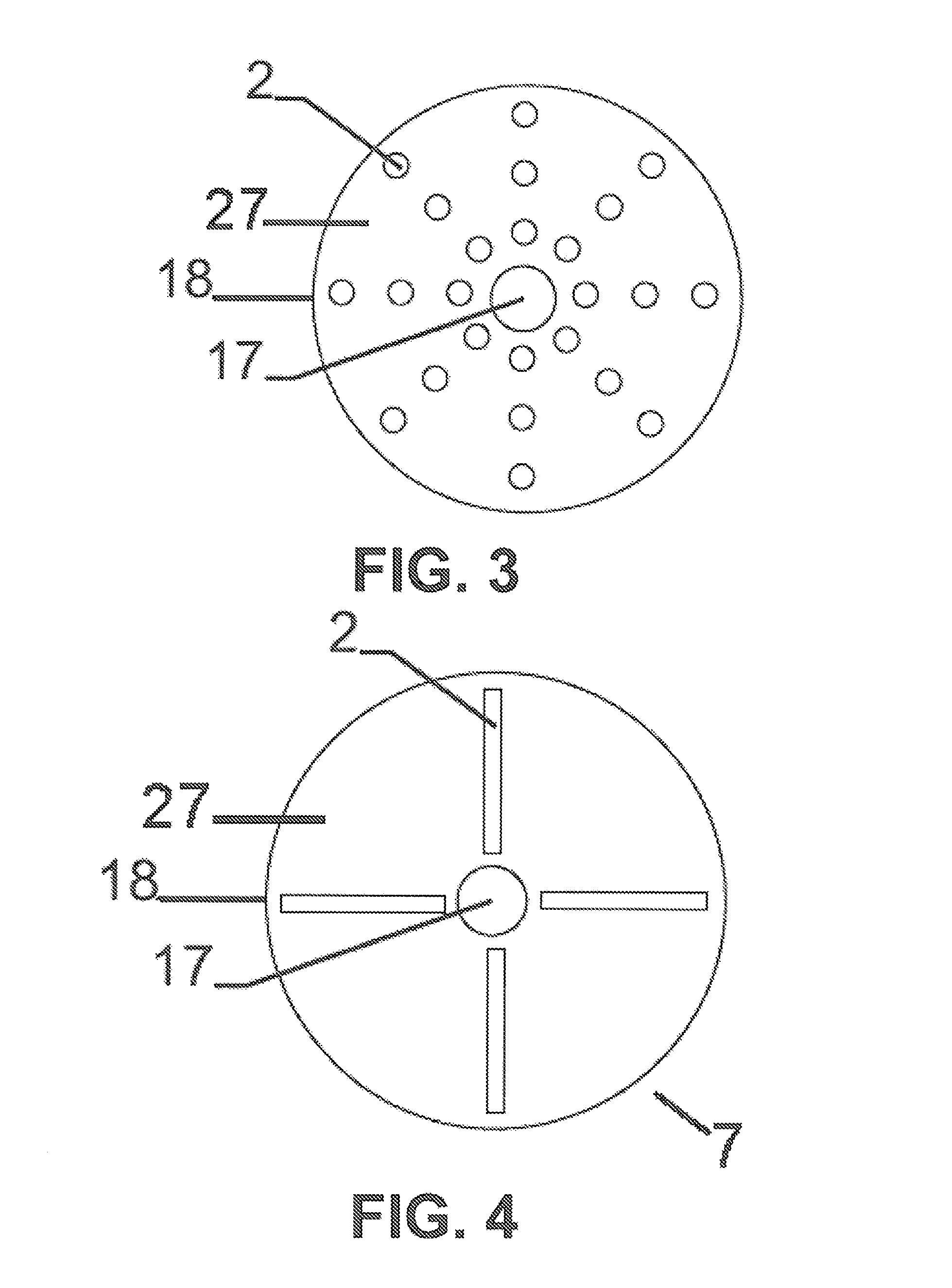
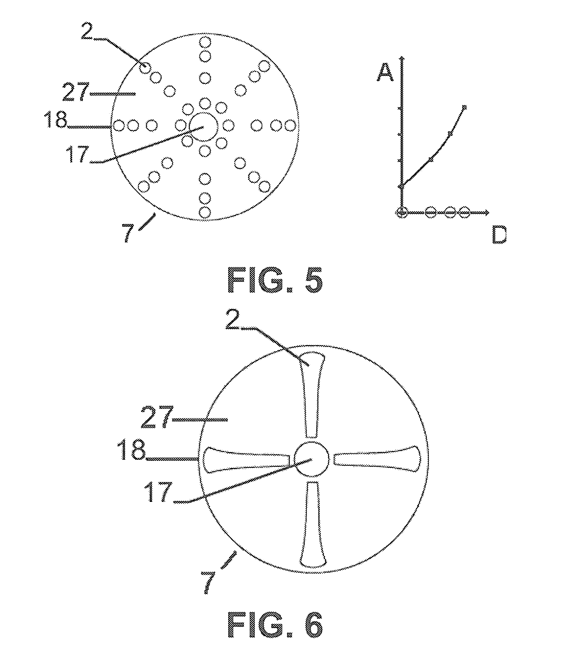
FIELD OF THE INVENTION[0001]The disclosure relates to an apparatus for cell culture, to a method of manufacture and operation of the same and to uses of the device for the culture of adherent cells, for the culture of stem cells or primary cells, for the culture of mammalian cells, and for the production of antibodies or viruses, such as for human and / or animal therapies or vaccines.BACKGROUND OF THE INVENTION[0002]Cell culture of eukaryotic cells that is commercially relevant can be divided into two classes: the cell lines and the primary or stem cells. The cell lines are relevant for the preparation of vaccines (viruses) and of proteins, e.g., antibodies. The cell is used as a bioreactor, the cell is thus nothing else than a host. It can be genetically engineered: one introduces into the cell a gene sequence whose gene product one desires to be produced by the cells. This class of cells can be grown in a fixed bed bioreactor such as disclosed in WO 2007 / 039600A, the disclosure of ...

Claims


Application Information

Patent Timeline
Patent Type & Authority Applications(United States)
IPC IPC(8): C12M1/00C12N7/00C12N5/00C12M1/12C12N5/02C12M1/36C12M1/34C12P21/04C12N5/071
CPCC12M23/22C12M41/46C12M25/06C12M25/02C12M3/04C12M1/14Y02P20/582C12M23/04C12M23/44
Inventor KARERANGABO, DIDIERCARDON, JULIENCASTILLO GONZALEZ, JOSE ANTONIO
Owner PALL ARTELIS
Why Eureka
Eureka Blog
Learn More