Anchored cardiac ablation catheter

a catheter and anchoring technology, applied in the field of anchoring cardiac ablation catheters, can solve the problems of complex ablation techniques, side effects of treatment, and reduced quality of life or present risks

Active Publication Date: 2013-03-07
ELECTROPHYSIOLOGY FRONTIERS SPA
View PDF6 Cites 44 Cited by
  • Summary
  • Abstract
  • Description
  • Claims
  • Application Information

AI Technical Summary

Benefits of technology

[0020]As a further feature of the apparatus and method, during catheter ablation procedures, Transesophageal Echocardiographic (TEE) Ultrasound is often used as a guidance tool for placing the ablator. The TEE instrument can also include an electrode for the return ablation energy circuit as described above. A minimally invasive device inserted into the esophagus can also contain one or more magnets, in which opposite-pole magnets can be included in the ablator device. Thus the TEE device can include magnets to enhance, or provide, the prime anchoring technique for holding the ablator against the target.

Problems solved by technology

Additionally, some drug treatments have side effects that reduce quality of life or present risks.
However, today's ablation techniques are complex and have not reached high efficacy, thereby limiting their clinical utility.
A particular problem is that clinicians cannot easily determine during the procedure whether the ablation produced is likely to interrupt conduction permanently.
However, of the approximately 1 million AF patients in the US not successfully treated with drugs, only about 100,000 are treated by ablation annually.
More are not treated by ablation due to its difficulty and the wide variation in treatment efficacy.
To achieve even these results, approximately 40% of patients require repeat procedures at significant cost to the healthcare system, along with the radiation exposure from imaging and other risks to the patient and to the clinician inherent in these procedures.
Market research indicates that both the variations in efficacy and the lengthy duration of the procedure are primarily due to uncertainty on the part of the clinician during the procedure as to whether the ablation lesion is continuous, complete, permanent, and transmural.
Their placement limits their application to only electrically isolating unwanted signals around the pulmonary veins from the rest of the heart.
Electrophysiologists, who perform the ablation procedures have also indicated that follow-up spots still need to be ablated, and there have been reports of injuries to surrounding tissue such as the phrenic and vagus nerves, and stenosis of the veins.
This increases procedure time and reduces the likelihood of generating a continuous, fully transmural ablation.
Because each ablator electrode in the array resides in a continuous ring, it may not satisfactorily conform to the target tissue's topography.
Point ablators take significant procedure time and do not necessarily generate continuous lesion lines to block unwanted electrical pathways.
In addition the robots are very expensive.
However, present methods and technology do not provide features for locating and fixing in place the ablative element(s) that are physically separate from the mechanism for performing the ablation.
This lack of separation limits the capability of devices based on these prior inventions to accurately locate the tissue volume to be ablated with respect to the pulmonary vein target at a location which minimizes the possibility of pulmonary stenosis, while also adjusting the contact of the ablative element(s) to provide intimate and accurate contact of the ablative element(s) with the atrial tissue and thereby form an ablated volume that fully encloses the ostium of the pulmonary vein.
These technologies are limited because they must be in continuous contact throughout the ablator-tissue contact range.
They have problems maintaining that contact during the ablation cycle.
However, this is a difficult procedure, which requires a high level of skill, exposes the clinicians and patient to radiation during imaging, extends procedure durations and reduces efficacy.

Method used


Image

  • Anchored cardiac ablation catheter
  • Anchored cardiac ablation catheter
  • Anchored cardiac ablation catheter

Examples


Embodiment Construction

[0056]An apparatus and method for performing cardiac ablation employs a catheter and various anchoring and ablation techniques, according to illustrative embodiments described herein. The various arrangements and types of apparatus components are shown in the illustrative embodiments of FIGS. 1-18.

[0057]A. Catheter Including Balloon Anchor and Compass Ablator

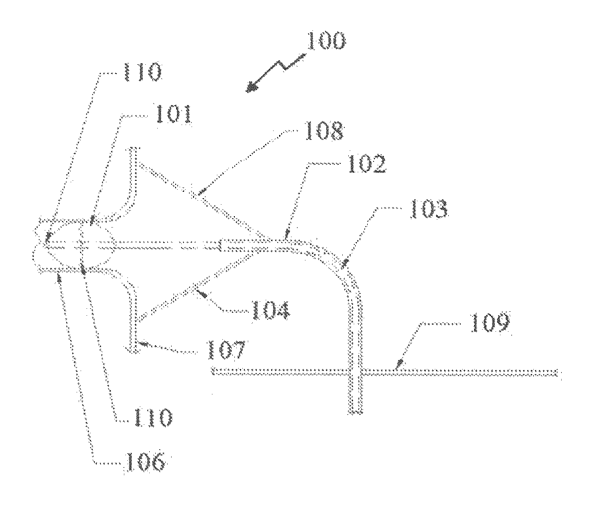
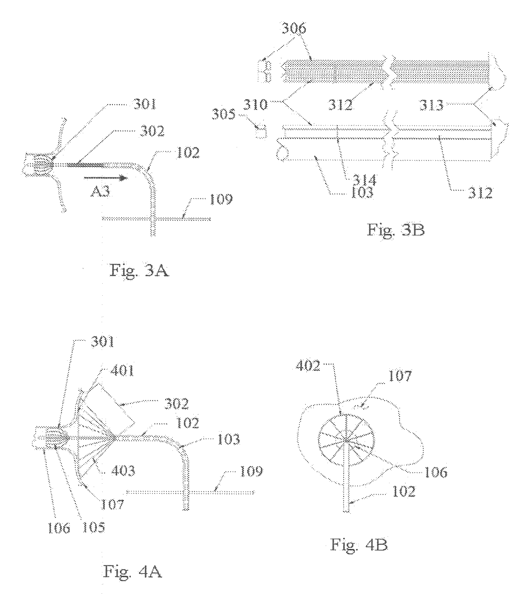
[0058]Reference is now made to FIGS. 1A and 1B showing, respectively, a side and front view of an illustrative embodiment of a cardiac ablation catheter comprising a point or “compass” ablator and balloon anchor. The point ablator is maneuvered circumferentially similar to a compass, thereby this embodiment is referred to as a compass ablator 100 includes a balloon anchor 101 at the distal tip 110 of the catheter 103. An “anchor”, as the term is used generally herein, refers to the structure assembled on a distal end of the catheter for application within the pulmonary vein. The anchor structure expands radially outwardly so as ...


PUM


Abstract

An apparatus and method for performing cardiac ablations employs a catheter comprising an anchoring device and an ablating device to perform the ablations to electrically isolate the pulmonary veins and left atrium from surrounding atrial tissue. The anchor can comprise a balloon-type device, a stent-like device, a strut-like device, a spring-strut-like device, an umbrella-like device, a mushroom-like device, or other device that allows the catheter to maintain a position with respect to target tissue. The ablator can comprise a balloon ablator, an umbrella ablator, a pinwheel ablator, an umbrella ablator incorporating a cinch mechanism, a mushroom balloon ablator and a segmented balloon or pinwheel ablator. The anchor and ablator can also comprise a combination mushroom balloon anchor section and mushroom balloon ablator section. The anchor and ablator can include electrodes for measuring a conductance therebetween when in deployed position, so as to determine the effectiveness of the ablation.

Description

RELATED APPLICATIONS[0001]This application claims the benefit of copending U.S. Provisional Patent Application Ser. No. 61 / 331,537, filed May 5, 2010, entitled ANCHORED RING CARDIAC ABLATION CATHETER, the entire disclosure of which is herein incorporated by reference.FIELD OF THE INVENTION[0002]This invention relates to cardiac ablation devices and methods for using the same.BACKGROUND OF THE INVENTION[0003]Atrial fibrillation (AF) is an arrhythmic condition of the heart in which the normal cardiac electrical impulses spread through the atrium in an incoherent manner, preventing the atrium from efficiently delivering blood to the ventricle. It is estimated that over 2.2 million Americans and 4.5 million EU citizens suffer from atrial fibrillation. Annual costs in the U.S. related to AF are approximately $16 billion. There are approximately 300,000 new AF cases each year. Contributors to AF incidence include the aging population, and many conditions including hypertension, cardiomyop...

Claims


Application Information

Patent Timeline
Patent Type & Authority Applications(United States)
IPC IPC(8): A61B18/14
CPCA61B18/1492A61B2018/0016A61B2018/00261A61B2018/00285A61B2018/00357A61B18/14A61B2018/00839A61B2018/00875A61B2019/465A61B2019/5263A61B2018/00577A61B2034/2063A61B2090/065A61F5/0127
Inventor SKLAR, MARTIN J.GUTHERMANN, HOWARD E.RING, HOWARD
Owner ELECTROPHYSIOLOGY FRONTIERS SPA
Why Eureka
Try Eureka