Data Centre Cooling Systems

a cooling system and data centre technology, applied in the field of data centres, can solve the problems of equipment overheating, typical data centre arrangement not particularly energy efficient, and ineffective cooling of a data centre, and achieve the effect of less of a risk of an unintentional increase in temperatur

Active Publication Date: 2013-03-14
BRIPCO
View PDF4 Cites 66 Cited by
  • Summary
  • Abstract
  • Description
  • Claims
  • Application Information

AI Technical Summary

Benefits of technology

[0086]The target value may be gradually increased over time to a final steady-state target value. By initially setting the target value to a value that is significantly lower than the final steady-state target value, the mechanical cooling system may effectively be run at a level significantly higher than the level that would be necessary to achieve the final steady-state target value in the most energy efficient manner possible. However, by over-driving the mechanical cooling system initially, there is less of a risk of an unintentional increase in temperature as a result of lag in the system. The mechanical cooling system may be run at a relatively high level temporarily in order to achieve the final steady-state target va

Problems solved by technology

One key problem faced is how to cool a data centre effectively and efficiently.
If the volume is not sufficient, then the servers can draw in warm air from other areas of the data centre, possibly resulting in the IT equipment overheating.
It will be seen that this typical data centre arrangement is not particularly energy efficient.
This system has the disadvantages that it requires a significant number of both fans and temperature sensors to be distributed around the data centre in order to achieve effective airflow control, and the simulation uses significant com

Method used


Image

  • Data Centre Cooling Systems
  • Data Centre Cooling Systems
  • Data Centre Cooling Systems

Examples


first embodiment

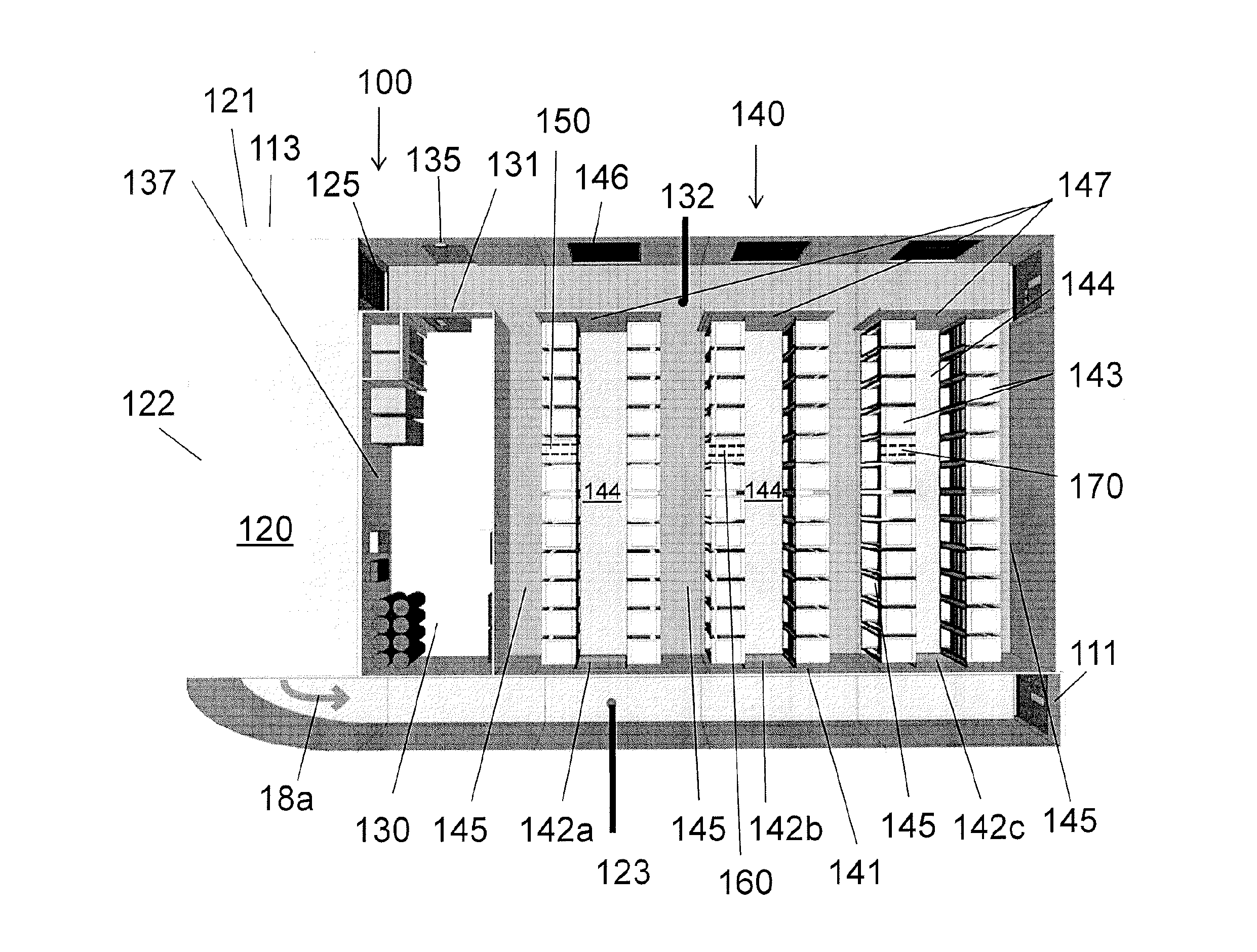
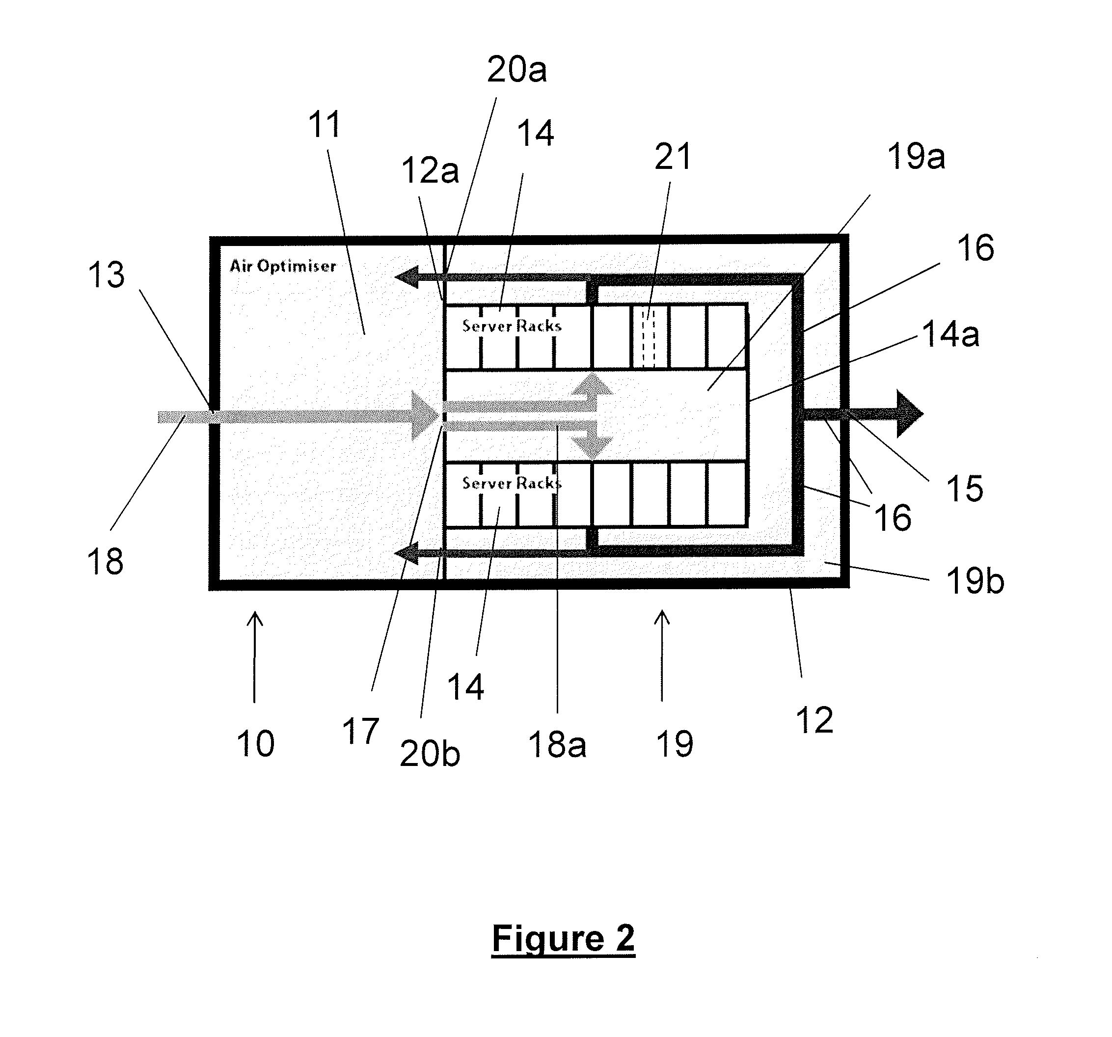
[0113]FIG. 2 shows a data centre building 10 according to the invention.

[0114]The building 10 is rectangular with external walls 12. The building is divided into front and rear sections by an internal dividing wall 12a, located approximately one third of the length of the building from the rear external wall.

[0115]The rear section (on the left in FIG. 2) defines an air optimisation room 11, which provides a system of circulating cooling air in the building 10. Ambient air 18 can enter the air optimisation room 11 through an ambient air intake 13 in the rear external wall. Exhaust air 16, which has been heated by IT equipment in the data centre, can enter the air optimisation room through two exhaust air intakes 20a and 20b in the internal dividing wall 12a. The ambient air intake 13 and the exhaust air intakes 20a and 20b are fitted with dampers so that the amount of ambient air and the amount of exhaust air entering the air optimisation room may be controlled. When the ambient air ...

second embodiment

[0120]In use, ambient air 18 enters the air optimisation room 11 through the ambient air intake 13 and / or exhaust air enters the air optimisation room through exhaust air intakes 20a and 20b. The air that enters the air optimisation room will from here on be referred to as supply air. The supply air can consist of just ambient air, just exhaust air, or a mixture of ambient and exhaust air depending on the position of the ambient air intake damper and the position of the exhaust air intake dampers. The supply air is cooled / treated as necessary in the air optimisation room 11 and leaves through air passages 17 as cooling air 18a. The treatment and / or cooling of the supply air may be effected in accordance with the second embodiment described below. The volume of cooling air leaving the air optimisation room is controlled by a variable speed fan (not shown) in the air optimisation room.

[0121]The cooling air 18a enters the rack room 19 into the cold region 19a. The cooling air 18a moves...


PUM


Abstract

A method of cooling a data centre having at least one hot aisle (145) and at least one cold aisle (144), including the steps of producing cooling air having controlled to have temperature and relative humidity within certain pre-defined limits; supplying the cooling air to a plurality of items of IT equipment (143) located in the data centre between the cold aisle and the hot aisle; measuring the velocity of air flowing from the hot aisle to the cold aisle through an opening (150) between the hot aisle and the cold aisle; and controlling the rate of supply of cooling air to the items of IT equipment in dependence on the velocity of air so measured.

Description

BACKGROUND OF THE INVENTION[0001]The present invention concerns data centres and a method of cooling equipment in a data centre. The invention also concerns apparatus for cooling a data centre.[0002]A data centre is a late 20th Century development that has grown as a response to the increasing demand for computer processing capability and a recognition of the importance of information technology (IT) in the place of every business and organisation today. Whereas smaller organisations have sufficient processing power with laptops, PCs and occasionally servers, larger organisations require higher capacity centralised processing to serve a wide range of needs and applications. A few years ago this capacity was supplied by large mainframe computers, but more recently the method used has been to provide data centres comprising many networked computer servers known as “blades” installed in racks enabling controlled and modular expansion of capacity. The racks also typically house storage ...

Claims


Application Information

Patent Timeline
IPC IPC(8): G06F1/20F24F3/14G05D23/00
CPCH05K7/20836H05K7/20745
Inventor VANEY, NICKKINGHAM, TOMBRITTON, SIMON
Owner BRIPCO
Why Eureka
Try Eureka